Report 7: The Temple of Artemis at Sardis (2020)
by Fikret Yegül
Chapter 2. Description of the Building. The Physical Remains
Surveying and Recording Conventions
The Temple of Artemis is assigned its own system of levels (“Artemis Temple datum”), independent of the B-datum adopted by the Harvard-Cornell Expedition in 1958 and widely used in Sardis since then. It also has its own location-reference conventions, which are independent of the official B-grid system. Each system can easily be converted to the other.
The top of the marble euthynteria at the southeast corner anta of the temple was given the reference datum *100.0, an arbitrary value. Thus, all elements of the superstructure are above this level, and all elements of substructure (mainly the foundations) are below (e.g., a wall top 60 cm above this level is *100.60; a foundation 30 cm below euthynteria grade is *99.70). A combination of curvature and soil settlements, affecting especially the long walls, have compromised this *100.0 datum at the euthynteria level as much as 5–7 cm (up or down), compelling us to indicate “heights” as directly measured from the euthynteria unless hard “elevation” values were established by independent survey (given in section-elevations with arrows, especially Plate 14-19 and Plate 20, Plate 21, Plate 22, Plate 23, Plate 24; given the variance in the field, these values and their concordances in the text are accurate within ca. 1–4 cm).
This system was devised by Hanfmann and his co-director A. Henry Detweiler, working with architects Thomas H. Canfield and Stuart L. Carter; although he thought it had been devised by Butler, it was not.1 In 1958 the south pteroma euthynteria level of the temple was found to be 138.38 meters above sea level (masl). In the same year the expedition established the B-datum on a concrete marker placed in the north apse of “Building B” (Roman Bath-Gymnasium Complex) at an arbitrary elevation of *100 m (not to be confused with the same number of the temple euthynteria), which is 115.11 masl (see Plan 1).
For plans, the Harvard-Cornell Expedition decided to incorporate the temple into the B-grid system in which the sturdy and well-preserved southeast corner of “Building B” was designated as “grid zero.”2 This system was used in the excavations, clearing, and recording operations inside and around the temple in 1969–73 and 2002–12. According to the B-grid, the temple platform is located between W100–197/S1215–1258; these values are approximate because the longitudinal axis of the temple does not align with the B-grid but rather veers some 2.2 degrees northeast/southwest. The anta-to-anta distances of the north and south walls run roughly 3 m askew from the B-grid alignment over their full lengths of 67.50 m. The grid value for the outer corner of the southeast anta pier is W112.9/S1248.3.
Influenced by the aesthetics of the temple’s impeccable orthogonal geometry, but mainly for reasons of measuring convenience, my study and drawings of the temple do not use the B-grid, and all my levels are based on the assumption of the northwest anta euthynteria as level *100.0. Instead, we used a simple grid based on the building’s main axes, taking our distances (wall lengths, etc.) to designated fixed points on the building, such as the well-preserved southeast and northeast anta pier corners (see Plan 4, Plan 5, Plan 6, Plan 7).3
Although Butler’s excavation of the temple produced accurate drawings based on many original measurements, the most extensive measuring and surveying work was accomplished during our survey of the building (starting in 1987), undertaken in order to create a full program of architectural documentation. We produced a full plan, sections, and elevations of the temple at 1:20 scale, which allowed us to record even minor details (Plate 8-13, Plate 14-19, Plate 20, Plate 21, Plate 22, Plate 23, Plate 24); we also undertook the creation of separate plans, sections, elevations, perspectives, axonometrics, detail drawings, and hypothetical (or “idealized”) restoration studies at 1:100, 1:200, 1:10, and 1:5 scales. These provide the measurements used in this publication. Our values on the whole are the same or close to Butler’s, but divergences are noted.
Having started the project before advancements in electronic and digital survey techniques, we used the optical transit and level (“dumpy level”) and the trusted tightly stretched steel tape, with many triangulations and back-checks in our measurements. In later years the main architectural features of the temple were resurveyed using a total station. We incurred discrepancies and errors in our drawings of around 0.10–0.15 m for the nearly one hundred meter length of the structure and distributed the error. This represents about 0.01–0.015 percent inaccuracy of recording over long distances (e.g., 1–1.5 cm over 10 m).4
The east end and the east porch—comprising fifteen columns in situ preserved to varying heights (columns 6 and 7 are preserved intact) as well as three column bases in the foundations, the southeast and northeast antae, and the south wall with its east door—form the best-preserved part of the temple, and they provide us with the most accurate physical and spatial (directly measurable) information about the building. In turn we are able to project those measurements onto the parts with poorer preservation and arrive at a credible reconstruction of the temple’s total design. Therefore, the features of the east porch and the east colonnade have been the subject of a special study (using steel tape); these direct measurements (with some minor reconstructions, e.g., of the eroded corner of a plinth) and triangulations are given in two special plans (see Plan 3, Plan 4).
Following Butler’s convention, the euthynteria, or the “ground level/foundation top course” of the main cella walls, is designated as 0; foundation courses below this level are designated as negative (thus one course below the euthynteria is −1); those above (as seen from outside, the pteroma side), as positive (thus one course above the euthynteria is +1). Since the interior of the cella is ca. 1.60–1.70 m higher than the outside, the bottom two or three courses (+1, +2, +3) on the exterior face of the wall appear to be foundation courses when viewed from the inside, with their unfinished faces below the floor level.
-

Şek. Plate 14-19
(Telif hakkı Sart Amerikan Hafriyat Heyeti / Harvard Üniversitesi)
-

Şek. Plate 20
(Telif hakkı Sart Amerikan Hafriyat Heyeti / Harvard Üniversitesi)
-

Şek. Plate 21
(Telif hakkı Sart Amerikan Hafriyat Heyeti / Harvard Üniversitesi)
-

Şek. Plate 22
(Telif hakkı Sart Amerikan Hafriyat Heyeti / Harvard Üniversitesi)
-

Şek. Plate 23
(Telif hakkı Sart Amerikan Hafriyat Heyeti / Harvard Üniversitesi)
-

Şek. Plate 24
(Telif hakkı Sart Amerikan Hafriyat Heyeti / Harvard Üniversitesi)
-

Şek. Plan 1
(Telif hakkı Sart Amerikan Hafriyat Heyeti / Harvard Üniversitesi)
-

Şek. Plan 4
(Telif hakkı Sart Amerikan Hafriyat Heyeti / Harvard Üniversitesi)
-

Şek. Plan 5
(Telif hakkı Sart Amerikan Hafriyat Heyeti / Harvard Üniversitesi)
-

Şek. Plan 6
(Telif hakkı Sart Amerikan Hafriyat Heyeti / Harvard Üniversitesi)
-

Şek. Plan 7
(Telif hakkı Sart Amerikan Hafriyat Heyeti / Harvard Üniversitesi)
-

Şek. Plate 8-13
(Telif hakkı Sart Amerikan Hafriyat Heyeti / Harvard Üniversitesi)
-

Şek. Plan 3
(Telif hakkı Sart Amerikan Hafriyat Heyeti / Harvard Üniversitesi)


Some Commonly Used Construction Features and Methods
The temple incorporates a rich collection of construction methods, practices, and features. Most are known practices in use across the larger Greco-Roman world, while some are more specific to their time and place, and still others are novelties created at the job site itself through the knowledge, flexibility, and creativity of masons and craftsmen. Above all there is great variance in these methods and features—field solutions interesting and ingenious. Despite the use of these methods and practices over a long period of time, it is nonetheless possible to arrive at least at a rudimentary understanding of their origins and chronology.
In our temple, notable differences in construction define the two major phases in the Hellenistic and the Roman Imperial periods. Before offering a summary account of the principles and characteristics of these phases, I present a general description of some of the commonly used construction features and methods; more detailed descriptions of these methods will be given in relevant chapters below.
Lifting: Standard and Carian Lewis Systems
One of the several lifting systems used in ancient construction is the lewis system.5 “Lewis” refers to a set of iron pieces (lifting irons/keys) that are wedged into and against the sloping surfaces of a socket (the “lewis hole”) made for this purpose. The standard type of lewis hole is a rectangular cutting with one or both sides sloping down (double-sloping or double-sided lewises are sometimes referred to as “dovetail” lewises), with the opening at the top narrower than the bottom of the hole. Occasionally, to avoid clumsiness or pedantry, “lewis” and “lewis hole” are used interchangeably or to refer to the system itself; the context makes the meaning clear.
All lewises work on the principle of friction and gravity.6 As described by Hero of Alexandria (active ca. AD 60) and verified by archaeology, there are two main lewis types: the standard lewis with rectangular hole (as described above) and the so-called Carian-Ionian lewis (originating in Caria).7 With rare exceptions, all standard lewises in the Temple of Artemis at Sardis belong to the Roman period and are of the double-sloping type. The Carian-Ionian type, limited in its use to between the fourth and the second centuries BC, is restricted to the Sardis capitals of the Hellenistic period.
The sloping, narrow sides of the lewis hole (“contact surface”) essentially carry the load when lifting irons are wedged tightly against its surfaces; theoretically, larger contact surfaces (i.e., larger and deeper holes) are capable of carrying heavier loads. It is logical to expect a basic proportional correlation between weight and lewis size, and this is borne out in the field in a general way: larger blocks, such as the architraves, display two—even four—symmetrically arranged, large lewises. Based on empirical evidence, the average-sized lewises of the temple were designed to carry 4–6 tons each; we have found no failed (or recarved) lewis holes.8 Average Roman column drums, weighing ca. 4–8 tons, could have been lifted by a large central lewis or a pair of smaller side lewises. The largest drums could weigh as much as 10–14 tons and would have required three lewises—a central one and one on each side. Yet, these figures are averages, with much flexibility and variance. As noted by Cahill, “Different crews could have different perceptions and comfort levels, or just different equipment.”9 These and other factors could explain the variance we find in the correlation between workload and lewis size/number; no scientific tests in the field have yet been made.
Less-common lewis arrangements used on some blocks consist of the crossing of a pair of lewis holes (“cross-lewis”) or T-shaped lewis holes (ca. 16–20 × 6–8 × 19–24 cm; Fig. 2.241, 2.242). It is unclear if these were original variations in order to increase the lifting capacity of a single lewis, or if each hole was used for separate episodes of lifting and setting—probably the latter.10 To ensure a balanced lift, all lewis holes were carefully positioned at the gravity centers of their blocks, but occasionally this rule was ignored or a smaller, outside lewis was added, possibly to maintain a third line to help tilt the block for exact placement.11 The Roman practice of lifting favored the standard lewis system instead of rope slings; in many instances, the tops of fluted Hellenistic drums reused in Roman construction were recut, with two or three added lewis holes (see in this chapter pp. 118–120). There is, however, at least one unfluted drum in situ (column 2, top drum; Fig. 2.183) which has no lewis holes at all—only a pair of small, square dowel holes. How was that piece lifted into place?
As a general rule, Greek and specifically Hellenistic period lewis holes, as we clearly see on some of the column drums of the Temple of Apollo at Didyma, tend to be smaller and narrower in proportion, and they display more careful workmanship than the Imperial period examples (Fig. 2.1; compare to Figs. 2.3, 2.38, 2.40, 2.240). At Sardis, standard Roman lewises are large and somewhat coarsely made. In a sense, a coarsely carved socket is as effective as a precisely carved one with smoother surfaces. As observed by Aylward, who undertook a special study of the Sardis lewises, “lewis sockets vary in size, shape, and method of carving across time and place,” especially during the Roman era, when lewises tended to display little consistency in design and workmanship, even in the same building.12
There is little doubt that both carving and operating a lewis system required some amount of specialist knowledge and skill. However, this must have been a technical specialization subsumed in a general way under the skills and expertise of masonry, not one that required exclusive cadres of “lewis workers” offering their exclusive knowhow intra sites and regions. Each site and building would have had its own skilled masons to carve a variety of lewis types on demand, just as those responsible for other specialized details, such as dowels, anathyrosis, and drafted edges. Based on our observations of the Roman lewises used in the Temple of Artemis, we suggest that a lot of the rough (but functional) lewis sockets were carved by apprentices under the supervision of their masters.
The Hellenistic capitals of the temple (capitals C, D, E, F, and G) feature an earlier lewis type known as the Carian-Ionic lewis, a type far less common and restricted in use at Sardis to the Hellenistic period (Figs. 2.259, 2.265, 2.268). The typical Carian lewis system consists of a small, narrow rectangular socket with double-slanting sides next to a larger one—often square—with straight sides.13 After the dovetail-shaped iron key was lowered and pushed into the slanted socket, a piece of wood was inserted in the depression of the straight socket to prevent the iron from sliding back out of its wedge hole. In the Carian system, the lewis key was a single piece specially made to fit the socket snugly, as opposed to the standard type, which used several iron keys together. The latter, obviously, had greater flexibility, since the same set of keys could be used in different lewis sockets as long as the size difference was not extreme. In the Sardis capitals, the nearly square straight socket is very large (ca. 26–29 cm) as compared to the small, rectangular slanting socket next to it (ca. 4–6 × 13–15 cm).
The earliest known use of the Carian lewis is in the Propylon of the Temple of Zeus at the Sanctuary of Zeus at Labraunda, and in an altered form (as a kind of a sideways dowel) at the Mausoleum at Halicarnassus, both productions of the Hekatomnid dynasty in Caria (hence the moniker “Carian”) and dating to the early to mid-fourth century BC Later examples from the third and early second centuries BC include buildings at Priene, Ephesus, Labraunda, Belevi, Miletus, Sardis, and possibly the Temple of Artemis at Magnesia. It was even used in Olympia for monuments dedicated by donors from Asia Minor. The type went out of use by the middle or end of the second century BC and was replaced by the more flexible and practical standard type; no known examples from the Roman Imperial period have been found.14
Among the scholars who view the period that started with the creation of the Mausoleum at Halicarnassus—and the slightly earlier monumental Hekatomnid tomb at Mylasa—as a distinct era for the flourishing of the arts, architecture, and letters in western Asia Minor, one singles out P. Pedersen as the most committed to and prolific on the subject. As Pedersen underlines, the fourth-century creative center of this movement, which he called the “Ionian Renaissance,” was Hekatomnid Caria; this could—perhaps more cogently conceived (as O. Bingöl kindly remarked in private conversation)—simply be called “the Carian Renaissance.”15 This is not the place to discuss the appropriateness of the name or the substance of such a “renaissance” or “revival,” as some prefer to call it. However, it is true—as Pedersen aptly demonstrates and archaeological discoveries verify—that Hekatomnid influence and patronage in the architecture of western Asia Minor during the fourth and third centuries BC was significant.16
The type of lewis described above (and named “Carian-Ionian”) was probably initiated and developed by talented craftsmen working in Caria and spread from there to other sites, including Sardis, with minor variations in design. Not only was the Carian lewis used exclusively on the Hellenistic capitals of the Temple of Artemis, but it was employed also on some ten preserved blocks of the roughly contemporary Metroon in the same city (IN63.118–21).17 This may demonstrate the simple popularity of this type of lifting technology in Sardis by the beginning of the third century BC (hence, the inclusion of Lydian Sardis in the technological and cultural koine of Ionia), but it does not indicate that Carian architects and craftsmen of the “Ionian Renaissance” were at Sardis carving their lewises and spreading a new and specifically Carian-based architecture in Lydia.18
Horizontal Joining: Clamps
Both of the primary methods of joining blocks horizontally are used copiously in the temple: the bar (or “hook”) and the butterfly- (or “dovetail-”) type clamps. Bar clamps consist of a plain metal bar (typically iron) with bent-down, bracket-like ends that “hook” into depressions in the stone. Lead poured over and around the clamp secures the bond between the clamp and the stone and protects the clamp from rusting. Butterfly clamps, wing-like in shape, are flat with no end hooks.19 They are commonly made of iron or bronze and set in poured lead, but they could be made of hardwood as well, especially in the larger sizes. (Average-sized butterfly clamps are ca. 12–15 cm long and 4–5 cm deep; larger sizes are ca. 26–30 cm long and 4–7 cm deep.) Although many iron bar clamps—with or without their lead settings—have been found in situ, none of the metal or wood elements of butterfly clamps have survived.
Hellenistic construction is characterized by bar clamps at or above the euthynteria level, but no clamps of any kind are used below the foundation levels of major walls. This general rule does not apply, however, to the column foundations inside the cella and the west pronaos porch, all of which are preserved below ground level and have small bar clamps. (Hellenistic bar clamps are typically ca. 10–13 cm long and 2–3 cm deep.) In contrast, Roman era construction utilizes butterfly clamps on foundation courses below the euthynteria level and regular bar clamps at courses at or above floor level. (Roman bar clamps are larger, averaging ca. 15–16 cm long and 4–5 cm deep.) Thus, butterfly clamps are used uniformly on the Roman east crosswall and the column foundations of the north and south peristyles (the latter in especially large sizes, ca. 22–28 cm long, 4–7 cm deep). The foundation blocks of columns 9, 15 (north peristyle), and 14 (south peristyle), which are at the pteroma level and prepared to support the column base plinth above them, have many bar clamps. This is also true for the above-ground level blocks of the west pronaos porch columns (53, 54, and 55). The blocks of the unfinished peristyle foundation courses have no clamps at all. The preserved top course of the west crosswall, a Roman construction, displays both butterfly clamps and bar clamps, sometimes on the same block. This might reflect the dual nature of this wall: the west face of its top course is above floor level and therefore finished, but the east face of the same course is unfinished because it was below the much higher floor of the cella. Although butterfly-type clamps are a feature of the Roman era construction of the temple, the use of this type goes back to the sixth and fifth centuries BC20 Butterfly clamps of the Classical and Hellenistic periods, as we see them on the Hekatomnid monuments of Caria (such as the unfinished “mausoleum” in Mylasa and the sanctuary of Zeus in Labraunda), sometimes with pegs in their ends, are among the most preciously crafted pieces of their kind.
Vertical Joining: Dowels
Several types of dowels, all well known in the classical world, were employed to secure vertical connections between courses at the Temple of Artemis. “Dowel” naturally refers to the connecting pin or peg, almost always of metal but sometimes hardwood, the latter especially in larger sizes. The dowel hole is the socket to receive the dowel, which is either circular (typically Hellenistic) or square in shape; some connections are secured by a peg with one square end and one round, although that type is not used in this temple. Here, circular dowels are commonly used in joining the fluted drums of columns, and they are located in the drum center; many were recut as central standard lewises in the Roman reuse of the drum.
Among the dowels employed between the ashlar courses of a wall or a foundation, a common type is the “edge dowel” (sometimes also known as the “side dowel”). The edge dowel is a Hellenistic feature used uniformly on the north, south, and east walls of the cella (clearly visible on the exposed west end foundations of the south wall); a few edge dowels also occur at the south and north ends of the middle crosswall (the original west wall) and on almost all of the foundation blocks of the cella’s interior columns (Figs. 2.2, 2.88, 2.90). The edge dowel hole is small and square (ca. 5 × 5 × 4–6 cm), on the top surface of a block, usually (but not always) paired with a slit-like cutting, or “leverage hole,” indicating the position of the course above. The edge of the upper block has a matching hole shaped like a three-sided notch (with an open front, facing the workman) which fits directly over the bottom dowel hole. The workman would then maneuver the upper block exactly into position with the help of a crowbar pivoting in the leverage hole. A square iron dowel peg would be placed inside the lower hole and lead poured through the open end of the upper dowel hole at the block’s edge, and the next block would then be pushed into place, covering the dowel and the leverage slit.21 This system allowed several crews to work at the same time as long as they were at different levels of the wall, those laying the lower courses ahead of those who were above them. The only Roman uses of edge dowels are seen at three random examples on the north end of the west crosswall (which normally employs regular dowels with pour channels; see below). These may have been exceptions, suggesting the possibility that some Roman masons tried this dowel system they learned from the earlier work on the temple—or, simply, that those blocks came from an earlier construction.
The dowel type common to Roman construction is the standard small square dowel with one, rarely two diagonally cut “pour channels” (ca. 10–18 cm long), or shorter “overflow” channels—two different though interchangeable methods.22 Such dowels can be seen on the west crosswall (Figs. 2.64, 2.68) as well as on the topmost foundation blocks of the north and south peristyle columns (9 and 14), where they are located at the four corners of the finished top course, ready to receive the plinth of the column base above (Figs. 2.114, 2.131). None of the other column foundations of the north and south peristyles (none was preserved at the topmost course) had any use for dowels. The three preserved column foundations of the west pronaos porch, on the other hand, have many dowels with pour channels on their topmost course (foundations 53, 54, and 55; Figs. 2.157, 2.158, 2.159). Dowel holes with pour channels are also visible on the preserved tops of the Roman era east door jambs, both those in situ and those inside the east cella (Fig. 2.36).
Some Hellenistic era elements, such as several of the Ionic capitals or the preserved fragments of the southwest anta capital, have dowel holes with pour channels, which are believed to have been recarved during their Roman era reuse (see pp. 127–128, 136–138) (Figs. 2.296, 2.297). The location of these dowels, at a short distance from the edge of the block (ca. 12–18 cm), allowed lead to be poured into the channel after the dowel pin was placed inside the hole and the upper block, with its matching dowel hole, lowered into place. In this case the poured and solidified lead formed a tight seal around the iron peg, also protecting it from rust. Such dowel holes are occasionally visible now if the joint was exposed because of a break or intentional gouging of the marble in order to rob the metals. Some of the pour channels were designed not to reach the edge of the joint (producing a cleaner joint). In these cases, “pour channel” is a misnomer because lead could not be “poured” from outside; it was simply a run-off, or “overflow channel,” for the expanding molten lead as the upper element was lowered onto the peg. When this kind of short channel was used to join the lowermost column drum with the top torus of a base, or in the joint between the torus and scotia of a base, a small lead lump can sometimes be seen (with difficulty) inside the deep cavities of the curving base moldings (Fig. 2.221). Dowels with pour channels must also have been used to join some but not all of the unfluted Roman era column drums, because in several places on the standing columns 6 and 7 the ends of the pour channels—and more dramatically, oozing lead—is still visible.
A third, less-common doweling method is known as the “dry dowel.” In this method the small, square dowel hole is lined by a bronze socket set in a very thin sheath of lead into which the bronze dowel peg fits tightly (“with no play”) without lead inside the casing.23 A tight-fitting square metal peg (probably bronze since no lead, normally to protect iron against rusting as well as to secure it, was involved) was inserted into the lower socket as the upper drum was lowered onto it, creating a tight fit without lead.24 Three Roman examples of this type of dowel can be observed on three unfluted drums (one south of Church M; another placed sideways on the south portion of the cella east wall; and the third a fragment preserving roughly one-quarter of the drum, now in the field southwest of the temple); a pair of square dowels with bronze sockets are placed symmetrically on either side of the drum’s center (Figs. 2.3, 2.4). This method does not use lead or pouring channels, avoiding any unsightly view of the channel between joints or lead spillage.25 However, the method required a very precise fitting of the upper and lower dowel elements since the slightest misalignment would not have been tolerated; the upper and lower dowel sockets and the iron peg must have been designed as a set. As seen on the drum next to Church M and the partial drum southwest of the temple, carefully drawn radial lines passing through the center of the drum and the dowel holes helped to ensure a precise match (Figs. 2.3, 2.4). Butler observed that the Sardis dowels on a lower drum and their matching sockets on the bottom surface of the upper drum were mates made for each other and “the pin and socket were mates . . . not easily [ever] interchangeable.” The process is no different than the precision design of bronze “astragals” (small feet or “bones”) for repurposed Egyptian obelisks which the Romans doweled into their bases, while the 400-ton obelisk was suspended on a lifting mechanism!26
The fluted drums of the Hellenistic temple re-cut and reused in the Roman building seem to have employed the same method: a pair of small square dowels without pour channels were cut on either side of the drum axis.27 None of these drums (now piled as a group at the west of the temple and elsewhere in the field), have metal casings—either they have been stolen or they never had them. Normally, the original fluted drums of the Hellenistic period were joined by circular bronze dowels or pins (none remains) set into single small, circular dowel holes in their centers (ca. 5 cm in diameter, 6–7 cm deep), a system also used in many Hellenistic temple drums in Asia Minor with bewildering variation, such as those of the Temple of Artemis in Magnesia on the Meander (single, central round dowel; single, central square dowel with one or two round dowels; or with a pair of standard, Roman-type lewises flanking a central, square or circular dowel); or the early to mid-third century BC columns from the Belevi Tomb (single, round central dowel; central round dowel with two asymmetrical round side dowels; large, square central dowel with one round side dowel; large square central dowel only; Fig. 2.5).28
Round dowels for what we believe to be Hellenistic construction have also been used in the Artemis temple to secure joints between capitals and architraves and perhaps, in a limited way, ashlar blocks of regular walls, the latter based on two examples found in the 1972 “trench 2” directly on the south side of the northeast anta pier.29 Of the five Hellenistic era capitals with sufficiently preserved tops, two (capitals E and F) display circular dowel holes with pouring channels at their corners (see below). We have no satisfactory explanation as to why this detail does not occur on the remaining three (capitals C, D, and G). It is possible that these small capitals from the cella interior carried wooden trusses due to the large central span across the cella (ca. 6.70 m clear, restored, ca. 9.30–9.40 m on axis, north–south; doubled wooden beams are another possibility) although the narrow lateral spans (ca. 5.40 m on axis, ca. 2.80–2.90 m clear) along the east–west length of the cella could have borne regular stone architraves (as shown in Fig. 4.14). Considering that none of the Roman era capitals (A and B, in situ on their standing columns 6 and 7), nor of the architraves—preserved whole or in pieces (all Roman)—display any dowel holes, we may assume that the circular corner dowels with pouring channels belong to the original features of the Hellenistic capitals. Roman era architraves of the temple relied on sheer weight for stability.30 Yet, the Roman builders were particular about additional vertical stability between column drums or between the top drum of a column and its capital, as they regularly introduced a pair of small, square dowels on either side of the original central round dowel of a fluted, Hellenistic drum (reused in Roman work), or on the bottom of a Hellenistic capital (as in capitals E and F).
An interesting feature shared by fluted and unfluted columns, but not fully explicable, is a large and relatively shallow square hole cut in the center of one or both ends of drums (ca. 12–16 cm square, 5–6 cm deep), as well displayed on the fluted drum sitting sideways on north peristyle foundation base 45 (Fig. 2.6; see also Figs. 2.192, 2.238). The type is familiar from a wide variety of column drums used in Hellenistic and Roman buildings (see example from the Belevi Tomb: Fig. 2.5). Having straight sides, they are obviously not lewis holes but probably housed large hardwood dowels. It is possible that a round hole in the middle of the wood could have held a round bronze pin and served as a central dowel. We have no clear evidence of this but similar arrangements are known; however, the square holes in these cases are invariably much smaller.31 A more interesting idea, which finds support from many colleagues and specialists, is that the wooden blocks could have served as a sort of axle to which a metal or wood pulling device could be attached for transporting column drums (like giant wheels) from the quarry to the jobsite. Vitruvius describes various versions of such arrangements for transporting column shafts or other large blocks—so-called Chersiphron’s machine—in book 10.12.11–12.32 Neither might be exclusive of the other.33
⁂
What has been described here is a large pattern of commonly used, conventional construction methods in our temple; some of these can be chronological indicators of Hellenistic- or Roman era work. There are, however, many exceptions to these conventions; variations and apparent inconsistencies of usage appear to be common rather than exceptional. For example, on the west crosswall, butterfly clamps constitute the majority (as expected for Roman construction) but there are also many bar clamps occurring side by side on the same block. On the same wall there are square dowel holes with pouring channels in association with leverage cuttings, but some without, and there are also some leverage cuttings independent of any dowel holes. These mixed methods and inconsistencies are occasionally the result of a reused block carrying construction features from an earlier use, later made nonfunctional, side by side with its newly carved construction features. However, they also reveal the flexibility available to the masons and work teams of the temple faced with daily field conditions. Wide ranges in the construction features of column drums, as detailed above with some examples, also support this observation. To summarize, some seven variants to the Roman reuse of the lewis on fluted, Hellenistic drum tops and seven on the unfluted drum tops have been documented, and not all can be explained by function. Showing flexibility and the ability to respond to different conditions, these variations may be more telling and interesting than the strict and mechanical adherence to rules.34
An All-Marble Temple
The temple is an all-marble building with few exceptional uses of limestone and sandstone. In its Roman phases, structural mortared rubble is also extensively used at foundation levels (see pp. 70–73). These lesser stones are used mainly under the door in the original west wall that gave access to the original cella and the door of the Roman era west cella in the late west wall. Substituting a weaker and cheaper material under thresholds of large openings was a fairly standard structural and economic expedience in ancient architecture (the wall under the Roman era east door in the original opisthodomos of the temple is, significantly, built in marble blocks). The foundations of the Hellenistic cella also incorporate some blocks of limestone and sandstone, although these are mainly reused blocks. The substructure of the image base located in the middle of the original cella (also referred to as the “basis”) is in purple sandstone; it is believed to be a feature predating the temple. In its use as the image base for the Hellenistic cella, no doubt it would have been faced in marble.
All-marble temples (walls, columns, and often most of the foundations) represent a great distinction or luxury associated with Greek architecture. The most prestigious of such temples, which reflect the wealth and pride of their communities, even boast all-marble roofs, such as the Parthenon in Athens, the touchstone for quality and luxury in Greek marble architecture. Although the Romans were more practical in their use of building materials and often substituted (effectively) marble veneer over cheaper stone and rubble construction, Roman temples in Greece and Asia Minor, lands renowned for the richness of their marbles, were also in marble. Thus, for the archaeologist and architectural historian, all-marble temple construction may appear less remarkable than it really should. We are somewhat inured to the expense and exceptionalism of solid marble construction. In a gigantic temple, such as we have in Sardis, the visual and intellectual impact of the sheer volume of marble that was quarried, transported, and shaped to create it is impressive (ca. 61,000 cubic meters for the Hellenistic cella; see pp. 201–204 and pp. 256–258).35
Based on simple visual comparisons of color, veins, and granular structure, it was long predicted that the marble for the temple might have come from local quarries known as Mağara Deresi, located in a deep ravine some 3 km south of the temple. The remains of an ancient road, extensive evidence of ancient quarrying, and the favorable higher altitude of the source (ca. 150–200 m higher than the temple) made this a likely proposition. These predictions were verified by the recent analysis of the quarry marble using minero-petrographic and isotopic analyses in comparison to marble taken from the temple as well as from other buildings at or near the sanctuary.36 Almost all of the marble used in the temple, in both its Hellenistic and Roman phases, falls within the same or very close ranges represented by the quarries, except for one reused block from the north wall of the temple, judged to be pre-Hellenistic by its construction features (extensive use of the flat chisel, butterfly clamp cuttings, and square dowels), which is petrographically “totally different” from the Mağara Deresi marble, “but similar to samples of Lydian architectural elements”—probably a piece from an earlier structure.37
The quality of Mağara Deresi marble is quite good. Judged by its granular structure (Maximum Granular Size [MGS]), it is comparable to Thasos and Marmara Island (Proconnesus) marble, significantly better than Naxos marble, but inferior to marble from Aphrodisias, Paros, Carrara, and not surprisingly, Penteli.38 Based on a reading of the verse inscription encircling the base of column 4, declaring “I am the first to rise . . . ” and referring to its base and torus composed of a single block of stone “furnished not by the people [demos] but by the ‘house’ (of the temple),” or made from “our own stones,” it is possible to suggest that at least some of the quarries were owned by the temple—facilitating the boasting of the column (see pp. 190–193). Since we know that the temple could loan money and undertake a mortgage transaction like a modern bank (as in the Mnesimachos inscription; see p. 163), the idea that the sanctuary could own such major resources is quite credible.
-

Şek. 2.241
(Telif hakkı Sart Amerikan Hafriyat Heyeti / Harvard Üniversitesi)
-

Şek. 2.242
(Telif hakkı Sart Amerikan Hafriyat Heyeti / Harvard Üniversitesi)
-

Şek. 2.183
(Telif hakkı Sart Amerikan Hafriyat Heyeti / Harvard Üniversitesi)
-

Şek. 2.1
(Telif hakkı Sart Amerikan Hafriyat Heyeti / Harvard Üniversitesi)
-

Şek. 2.3
(Telif hakkı Sart Amerikan Hafriyat Heyeti / Harvard Üniversitesi)
-

Şek. 2.38
(Telif hakkı Sart Amerikan Hafriyat Heyeti / Harvard Üniversitesi)
-

Şek. 2.40
()
-

Şek. 2.240
(Telif hakkı Sart Amerikan Hafriyat Heyeti / Harvard Üniversitesi)
-

Şek. 2.259
(Telif hakkı Sart Amerikan Hafriyat Heyeti / Harvard Üniversitesi)
-

Şek. 2.265
(Telif hakkı Sart Amerikan Hafriyat Heyeti / Harvard Üniversitesi)
-

Şek. 2.268
(Telif hakkı Sart Amerikan Hafriyat Heyeti / Harvard Üniversitesi)
-

Şek. 2.2
(Telif hakkı Sart Amerikan Hafriyat Heyeti / Harvard Üniversitesi)
-

Şek. 2.88
(Telif hakkı Sart Amerikan Hafriyat Heyeti / Harvard Üniversitesi)
-

Şek. 2.90
(Telif hakkı Sart Amerikan Hafriyat Heyeti / Harvard Üniversitesi)
-

Şek. 2.64
()
-

Şek. 2.68
(Telif hakkı Sart Amerikan Hafriyat Heyeti / Harvard Üniversitesi)
-

Şek. 2.114
(Telif hakkı Sart Amerikan Hafriyat Heyeti / Harvard Üniversitesi)
-

Şek. 2.131
(Telif hakkı Sart Amerikan Hafriyat Heyeti / Harvard Üniversitesi)
-

Şek. 2.157
(Telif hakkı Sart Amerikan Hafriyat Heyeti / Harvard Üniversitesi)
-

Şek. 2.158
(Telif hakkı Sart Amerikan Hafriyat Heyeti / Harvard Üniversitesi)
-

Şek. 2.159
(Telif hakkı Sart Amerikan Hafriyat Heyeti / Harvard Üniversitesi)
-

Şek. 2.36
(Telif hakkı Sart Amerikan Hafriyat Heyeti / Harvard Üniversitesi)
-

Şek. 2.296
(Telif hakkı Sart Amerikan Hafriyat Heyeti / Harvard Üniversitesi)
-

Şek. 2.297
(Telif hakkı Sart Amerikan Hafriyat Heyeti / Harvard Üniversitesi)
-

Şek. 2.221
(Telif hakkı Sart Amerikan Hafriyat Heyeti / Harvard Üniversitesi)
-

Şek. 2.4
(Telif hakkı Sart Amerikan Hafriyat Heyeti / Harvard Üniversitesi)
-

Şek. 2.5
(Courtesy S. Ladstätter, Österreichisches Archäologisches Institut.)
-

Şek. 4.14
()
-

Şek. 2.6
(Telif hakkı Sart Amerikan Hafriyat Heyeti / Harvard Üniversitesi)
-

Şek. 2.192
(Telif hakkı Sart Amerikan Hafriyat Heyeti / Harvard Üniversitesi)
-

Şek. 2.238
(Telif hakkı Sart Amerikan Hafriyat Heyeti / Harvard Üniversitesi)


An Overview of Hellenistic and Roman Construction and Major Phases
The original Hellenistic period construction displays carefully shaped and fitted blocks, and it uses bar clamps sparingly; for the main walls clamps are never used in courses below grade, where all blocks are tightly and intricately fitted without mechanical aid. Their use above grade (as in the foundations of the cella interior columns) favors the simple bar- or hook-type of clamps in smaller sizes (for a detailed discussion of major construction techniques and their chronological importance, see pp. 28–35 and pp. 165–174 above). It makes no use of lewis holes for lifting blocks except the capitals, which employ a different style of lifting hole, known as the Carian-Ionian lewis (see above). Dowels for the fluted column drums are small, circular, and placed on the drum center; square dowels positioned on the side or edge of the block (edge dowels) without pour channels are used for ashlar walls and foundations.
Roman period construction displays coarser blocks fitted with less care. Core construction is noticeably shoddier, filled with smaller, irregular blocks. Lewis holes are used commonly even for relatively small blocks. Clamps, which are copiously used (often joining blocks from all four sides), are both of the butterfly and the bar type, though the former is the norm for courses below the euthynteria level; bar clamps are reserved for courses at or above.
The Hellenistic phase of the temple consisted of only the cella, defined by its west front wall with a door (now the “middle crosswall”), the blank east back wall (opisthodomos), and the north and south long walls. Archaeological evidence indicates that the east pronaos had pairs of columns in antis, later removed; this might well have been true for the west pronaos as well. The cella interior (ca. 1.60–1.70 m higher than the pteroma) had two rows of twelve columns to help support the roof; these are preserved only in their foundations. The original base for the cult image (“basis”), a feature that predated the temple, is preserved in purple sandstone foundations in the middle of the cella. During the Roman phase the cella was divided into two nearly equal chambers by a wall 90 cm thick (“east crosswall”) in order to accommodate the imperial cult. A new door was cut in the east wall and stairs were built to provide access into the new east cella. The west cella was expanded by obliterating the original west wall of the temple and building a new west wall with a door (“the late west crosswall”) and stairs (or the original west door and its stairs were moved and reused). Since the new west cella straddled the western end of the original cella and a part of the west pronaos, creating a major discrepancy in floor levels, the lower pronaos was filled up; the columns in this hybrid area (four from the cella and four from the pronaos) were obliterated and replaced by a new interior support system (see pp. 204–205). This operation must certainly have required the overhauling of the roof structure of the new west cella and perhaps the east cella as well; a number, or even the majority, of the fine original marble roof tiles might have been replaced (Figs. 1.14, 1.15). Over time, the Roman phase also saw the building of the well-preserved columns of the east end and the projecting east pronaos porch, some or all of the columns of the west pronaos porch, and most of the foundations of the south and north colonnades.
-

Şek. 1.14
(Telif hakkı Sart Amerikan Hafriyat Heyeti / Harvard Üniversitesi)
-

Şek. 1.15
()


The Walls
South Wall
(plans: Plan 6, Plate 1, Plate 8-13; elevations: Plate 4, Plate 14-19)
The south wall of the cella is 67.50 m long between the southwest and southeast antae; its proper thickness at the orthostat level is 1.93–1.94 m. The wall is preserved at its eastern end at a height of 4–5 m in six or seven courses (for a length of ca. 14 m starting at the southeast anta pier, highest at *104.66; Figs. 2.7, 2.8, 2.15, 2.17, 2.18); in the middle, it is preserved at 0.50–2.0 m high in one to three courses (14–44 m); and at its western end at euthynteria level at *100.0 or lower, at foundation courses ranging from 44 to 67.5 m (for the foundations of the south wall see pp. 57–58 below). All the main walls of the cella, interior and exterior, are finished by gradations of fine claw chisel mixed with flat chisel, or chisels, manipulated in different directions.39 These features are well preserved and visible on a long stretch of the eastern end of the north wall (Figs. 2.19, 2.26, 2.31). A remarkable construction feature on the south face of the south wall is the series of short, incised lines (ca. 1–1.5 cm long) appearing at intervals on the upper surface of the wall socle (or toichobate, just below the torus molding) and marking the locations of the peristyle columns. The distance between each line is ca. 4.98–5.02 m, accurately marking the center positions of each column (now preserved only in their foundations), for a length of 35.04 m measured from the corner of the southeast anta pier.40 Since the peristyle columns belonged to Roman construction, the Roman mason must have (very practically and cleverly) used the smooth face of the Hellenistic cella wall for an accurate measure of the column positions.
What follows is a detailed description, moving from west to east, of the construction features of each course.
Course −2: For a stretch of ca. 8 m from the southwest anta—which is preserved only as foundations—the wall is represented by two courses below pteroma level (ca. *99.30–99.35) and varies in width 3.0–3.40 m (Figs. 2.9, 2.10). It is composed of very large blocks tightly fitted and smoothly finished with a fine pointed chisel. The blocks are quite uniform in size and distribution; they mainly consist of large, rectangular shapes, without small or irregularly shaped pieces as middle fill for the wall. This course reveals no lewis holes for lifting, nor clamp holes for joining the individual stones. Small, square dowel holes (6 × 6 or 6 × 7 cm, 3–4 cm deep) occur infrequently, and only along the outer edges of the blocks. At the western end, the outline of the foundation course supporting the southwest anta pier (course −1; Fig 2.11) is indicated by nine dowel holes—two along each side and five in front. This end also shows three incised mason’s marks roughly in the center and ends of the foundation course alignments below the anta proper. Leverage holes (prying holes) occur occasionally along the sides or in the middle of this course, indicating the alignment of the blocks above them. Primarily, the stability of course −2 is provided by the well-shaped and tightly fitted construction, the whole foundation kept in place by the buttressing of the earth into which it was laid (Fig. 2.12).
Course −1: The top surface of the course below the pteroma level is visible for a length of 3.80–4.0 m (57.50–61.0 m measured from the southwest anta pier); it is 2.70–2.80 m wide, with its top at *99.67. Without lewis and clamp holes it has a similar construction to the course below it. Square dowel holes positioned ca. 0.10 m inside the outer edge of the wall are paired with the upper dowel holes carved on the bottom of the course above (“edge dowels”).
Course 0 (euthynteria course): The top surface of course 0 is visible for a stretch of about 16.0 m (44–60 m from the southeast anta pier). This top foundation course is 2.60–2.65 m in width, with its top at *100.00. Its south face, roughly at the ground level of the pteroma, is fairly smooth and regular and projects ca. 10–14 cm outside the face of the finished wall above. Well below the floor level of the cella, its face is left rough and irregular (Fig. 2.20). Construction is similar to the foundation courses below; the surface is even and uniform with smooth, point finish; blocks are large and tightly joined without a distinct middle zone construction. There are no lewis holes but rather clamp holes of the hook type 18–23 cm in length, positioned along the edge of the wall and joining the blocks laterally on the exterior side, rarely on the interior side. No clamps are used to tie the blocks internally, across the thickness of the wall. Clamps are placed along and 30–32 cm from the south face of the wall. This is also the course where square dowel holes are regularly paired with leverage holes, each pair located ca. 30 cm from the south edge, and more or less in the middle of the block (which indicates the exact position of the course above, just at the edge of the leverage hole and covering the dowel hole). The leverage cuttings are on the west sides of the dowel holes, suggesting that construction of the course above moved from east to west.
Course +1 (first course of the wall above the foundations): The upper surface of course +1 is visible for a length of about 6.0–7.0 m (37–44 m from the southeast anta pier), 2.30–2.35 m thick, and 0.50–0.51 m high, with a top elevation at *100.51. This lowest first course of the wall proper projects 2 cm beyond the face of the course above it, creating a decorative offset. Both courses display a smoothly finished outer face (different grades of fine claw chisel); their inner faces, left rough, are well below the cella floor level. Exterior vertical joints, where finished, are extremely tight because of the use of anathyrosis, but many have a rough, vertical band, left unfinished to protect the joint (Figs. 2.14, 2.15, 2.17). The thickness of the wall is composed of, essentially, two rows of blocks: an outer, southern row, tightly fitted against an inner one. Large clamps of bar type, 33–34 cm long, are used to secure only the outer row of blocks laterally, situated 22–24 cm from the edge. Also forming a row at about the same distance from the edge are pairs of square dowel holes and leverage holes; a few dowel holes also occur along the interior edge, though these are not paired with any leverage cuttings. The leverage cuttings of the outer row (only five examples are visible) are located on the eastern side of the dowel holes, indicating that construction moved from west to east (the opposite of course 0 below it). No lewises have been used.
Course +2: The second course above the euthynteria is 2.02–2.03 m wide and 0.58 m high, with its top at *101.10. The outer face has a handsome torus-shaped crown molding, which is finished (except for the southeast anta base; Figs. 2.8, 2.14); the inner face of the course, although still below the cella floor level, is finished with a point chisel. The top surface of the course, visible for a length of about 15 m (22–37 m from southeast anta pier), shows a departure from the construction style of the course below it. There is a clear inner and outer “facing” of the wall displaying roughly rectangular blocks laid lengthwise (east–west), with a middle area filled with smaller, irregularly shaped and sometimes broken and reused blocks. The top surface has a moderate to fine point-chisel finish (Fig. 2.16). The facing blocks, outside and inside, are joined together laterally by bar clamps (outside clamps are situated 22 cm from the edge; their lengths vary 23–30 cm). There are no lewis holes even though some of the blocks are quite large (1.20–1.60 m long). The exterior south face of course +2 shows excellent workmanship with a fine claw-chisel finish, and razor-tight vertical joints with anathyrosis (Fig. 2.15).
Course +3: With a height of 0.88 m, course +3 is the orthostat course on the outside; inside it is backed by two courses, each 0.44 m high, with a top, outside elevation at *101.99. The wall thickness is 1.94 m. The top course has a nearly smooth, fine claw-chisel finished interior face; this would have been the first course (dado) visible above the cella floor paving. The top surface of this course is visible for a stretch of only 5–6 m. Both the outer (orthostat) and inner blocks are laterally joined by bar clamps; where visible, the inner blocks show the pairing of dowel and leverage holes—the latter on the east side—indicating that construction moved from west to east (also true at the orthostat level of the north wall). There is little to no use of middle-fill blocks; there are no lewis holes. The outer face of this course has a bottom molding of a simple fillet and apophyge and a very fine claw-chisel finish. Vertical joints are smooth, polished, and extremely tight. Some of the orthostates are 2.80–3.0 m long, making them the largest ashlar blocks preserved anywhere in the cella construction.
Course +4: The second course above the cella interior paving (and the fourth above the exterior pteroma) is preserved for a length of 14.50–15.0 m from the southeast anta pier corner, with its top at *102.56–102.60. The top surface of only one interior block of course +4 is visible, revealing a construction of inner and outer blocks joined by a thin, middle fill, lateral clamps, and square dowel holes paired with leverage holes. There are no lewis holes. The exterior surface reveals a fine claw-chisel finish and tight, smooth vertical joints.
Courses +5 and +6: Both of these courses are preserved for a length of about 14.50 m from the southeast anta pier corner; they are 0.70 m and 0.60 m high, respectively. The top of course +6 is at *104.06, and only the top of the inner blocks of course +5 is visible, for a stretch of ca. 5 m; it shows only lateral clamps and paired dowel holes and leverage holes. Both have inner and outer ashlar facings with a middle core of irregular and smaller blocks (Fig. 2.18). The inner corner of the east wall of the cella is structurally bonded into course +6 of the south wall; corner blocks are also clamped together. The exterior of course +5 and course +6 (and presumably all other courses above these) display drafted edges: the periphery of each ashlar block is drafted smooth 1–2 cm wide; the center is finished with a very fine claw chisel and slightly raised. The third block from the west of course +6 is not in situ but rather was placed in this position by Butler (with a large lewis hole in the middle and three half-clamp holes of the butterfly type, it was probably an original block of the cella but reworked later to be used somewhere else in the building).
Course +7: This third course with drafted edges is preserved for a length of 4.40–4.60 m and mainly defines the southeast anta of the cella, with its top at *104.66. Standing ca. 4.66 m above the pteroma, this is the highest-preserved level of the south wall. The westernmost block, probably not original, has a “half interior” clamp. The top surface of course +7 displays the usual arrangement of lateral clamps of the bar type along the outer and inner sides of the wall, and paired square dowel hole and leverage hole combinations. Leverage holes are positioned on the west side of the dowel, indicating that construction moved from east to west, i.e., from the end of the anta toward the junction of south and east walls, a situation also observed in the north wall of the cella. There are no lewis holes.
The inner face of the eastern end of the south wall defines the inner face of the southeast anta and faces the east porch of the cella for a length of 5.60–6.0 m (Figs. 2.20, 2.29). Thus, courses +1 to +7 correspond to those seen from the outside and, like them, display very fine claw-chiseled surfaces with precise vertical joints. The bottom two courses (+1 and +2) constitute the dado and the course with the torus molding. The two courses above them (the orthostat/course 0 and course +4) have fine claw chisel–finished surfaces; the top three preserved courses (courses +5, +6, and +7) have drafted edges. The end of the southeast anta base, arranged as a giant pilaster-pier, projects beyond the wall surface and displays a partially finished base molding of the Attic-Ionic type (Figs. 2.15, 2.18).
As is consistent with other original Hellenistic construction, there are no lewis holes in the Hellenistic construction of the south wall, except for its western end extension for a length of 7.50–7.60 m from the face of the southwest anta (preserved at two courses below euthynteria level); this is, of course, the Roman addition to the wall. These large Roman lewises are of the standard type (ca. 15 × 6.5 × 11.5 cm).
North Wall
(plans: Plan 6, Plate 1, Plate 8-13; elevations: Plate 4, Plate 14-19; Fig. 2.110)
Like its southern counterpart, the north wall is 67.50 m long between the northeast and northwest anta piers. While the northeast anta is preserved to three or four courses above ground (maximum height at its eastern end at 2.74 m, top at *102.74) and intermittently at only two courses, the wall drops down to a single course 59 m west of the northeast anta, top at *100.48–100.51. Only the euthynteria and the foundation courses below the pteroma level (courses −1 and −2) are preserved 64.5 m west of the same point. The interior connection of the northeast anta and northeast anta pier with the east wall is well preserved (Figs. 2.20, 2.31, 2.32). Nothing of the northwest anta remains above ground, though its northwest corner is clearly marked on the euthynteria. The north wall at orthostat level is 1.94 m thick.
The western end of the north wall directly under the missing northwest anta pier is exposed at euthynteria level (course 0) for a length of ca. 3.50 m (or, 64.0–67.50 m measured from the northeast anta pier) and has a foundation width of 3.45 m. The exposed part shows large blocks joined along their outside edge by three large hook clamps (29–30 × 8–9 cm) to the east end of the Roman era foundation block of column 48. These blocks also have edge dowels joining the first course of the northwest anta pier (13 × 7 × 4.5 cm). The top surface of this course displays a fine point–chiseled finish on which L-shaped incisions and faint setting lines mark the northwest and southwest corners of the anta pier. The southern (inner) face of this course and the two foundation courses below it (courses −1 and −2), are left rough and project out in steps.
The foundation course below the euthynteria (course −1) of the northwest anta juts out and extends west, making a continuous joint (or dividing line) between the Hellenistic and the Roman constructions (see pp. 87–88). It is connected by butterfly clamps to the foundations of column 48 but not bonded. The blocks on the Roman side of the construction are joined to one another with the same large butterfly clamps, and some display lewis holes; there are no lewis holes on the Hellenistic construction. This course, which is below the euthynteria, creates a space about two meters wide between the blocks that support the northwest anta and column 48; the distance between the reconstructed anta at the base and plinth of column 48 (in situ) is 2.38–2.40 m, exactly the anta-to-column-plinth distance for the fully preserved east side antae. This system of continuous or joining block foundations between an anta and the column before it, also true for the southwest anta and column 49, is different from the east-end system, where there is a void between the antae and the columns in front of them (columns 16 and 17; see below). The 2.08 × 3.50 m stretch of course −1, visible between the northwest anta and column 48 (see Figs. 2.107, 2.153), represents the physical joining of two period constructions: the eastern blocks are essentially a continuation of the foundations of the north wall and the western blocks represent the Roman addition. Leading up from the northwest steps and serving as the main passageway into the porch of the temple, the surface (top at *96.62) has been worn smooth by pedestrian traffic.
Course +1: The top surface of the first course above the pteroma is visible for a length of about 5–6 m (59–64.5 m from the northeast anta pier). This is also the stretch where the west crosswall of the cella wall joins the north wall. The course is 0.51 m high, with a two-centimeter projection beyond the face of the course above it (top at *100.51–100.52). The north face of this course for the entire length of the wall is well preserved with a fine claw-chisel finish and tightly fitted, smooth vertical joints. The construction of this course is characterized by large and carefully fitted oblong blocks for the outer and inner faces of the wall, joined laterally by bar clamps on the exterior and interior sides. The middle of the wall (at this course) is filled with smaller, irregularly shaped blocks. The surface is smooth with a fine claw-chisel finish or, in some stretches, very fine point-chisel work to allow for a smooth contact surface with the course above it. As in the south wall (typical of Hellenistic construction), there are combinations of small, square dowel holes with leverage holes, situated more or less in the middle of each block (dowel holes measure ca. 6 × 6 or 7 × 7 cm, 5–6 cm deep). On this course, as well as the ones above it, leverage holes are placed east of the dowel holes, indicating that the blocks of the course above them were laid from west to east.
Course +2: This course, 0.58 m high and characterized by its exterior torus molding, is exposed fully or partially for a length of 25–26 m (35–39 m from the northeast anta pier), with the top at *101.08–101.10. The long exterior face is carefully finished by claw chisel and has razor-sharp vertical joints achieved through the use of anathyrosis (in a few places where the end of a block is exposed, the mirror-smooth polish of anathyrosis and edge-dowels can be seen; Fig. 2.21). However, the horizontal joint between courses +2 and +3 (above the bottom torus molding) along the north face of the wall is unusually wide (ca. 2–3 mm), as Cahill commented in conversations in 2018, “The lead sheet visible in the [same joint of the] northeast anta explains this otherwise unique feature.” We do not have parallels for such joint construction, except for the joint between the torus and scotia of column base 13, where the presence of a thin lead sheet is barely visible (see Fig. 2.222), and we know neither its details nor its purpose or the advantage it offers. The heavy but delicate blocks have not been lifted or tilted to explore the joint.
The second course is not visible inside the cella, as it is below the paving level. Like the course below it, the exterior and interior faces of the wall are composed of larger regular, rectangular blocks of 1.20–2.0 m length; the middle fill is made up of smaller, irregularly shaped stones laid in rows (Figs. 2.22, 2.23). Both the exterior and interior blocks are joined laterally by bar clamps, those of the outer face being slightly larger than those of the inner face (ca. 28 cm vs. ca. 24 cm in length). Commonly used are the pairs of small square dowel holes and leverage holes (Figs. 2.24, 2.25). A curious feature of this course is the existence of eight long, slit-like dowel holes (8–12 cm long, 3 cm wide, and ca. 1.20–1.30 m apart) at the west end. Sharply and precisely cut, one of them still preserves its bronze socket. This distinctive—and apparently earlier—dowel type seems to be independent of the usual square dowels (paired with leverage holes), not a substitute for them. This unusual feature has no obvious or rational connection to this Hellenistic phase of wall building, except that they might have been a preexisting feature of these blocks.41
Course +3: The orthostat course, 0.87 m high, with its top at ca. *101.98 and varying in width (0.45–0.60 m), is preserved for nearly the entire eastern half of the cella north wall (0–26 m), then intermittently along its western half. The inner face of the orthostates, at the junction the wall makes with the original west wall of the cella (49–53 m), facing the Hellenistic pronaos area, carries the Mnesimachos (“mortgage”) inscription (see Figs. 2.53, 2.54, 2.55, 2.56). The inner (southern) faces of the orthostates of the cella interior are backed up by double courses, 0.46 m high at bottom and 0.41 m high at top. The inner face of the bottom course, the foundation, is left rough and projects as a ledge 12–15 cm into the cella; the paving was laid on this ledge. Clear impressions of mortar bedding for paving blocks are still preserved on the inner face of the north wall in the northeast corner of the cella, a rare instance of direct evidence for the finished cella floor at *101.60–101.69 (Figs. 2.32, 2.33). The course above the “dado” course of the cella interior is finished smooth and makes a two-centimeter decorative projection beyond the face of the course above it (course +4). Both the orthostates and the large blocks backing them are joined laterally by bar clamps (26–28 cm long) and display the usual pairing of square edge dowels with leverage holes. There are no lewis holes. Along some of the stretches of the north wall, the irregular and small blocks of the middle fill can be seen, although for the most part the outer- and inner-facing blocks are very large and join the orthostates directly. The outer (orthostat) face of this course shows gradations of finish, from the work of a coarser claw chisel to that of a finely finished claw or flat chisel, and tight vertical joints (Fig. 2.26).
Course +4: This course is 0.76 m high and 0.60 m wide, and is preserved for a length of 8–9 m on the exterior of the eastern end of the cella (4.50–13.50 m from the northeast anta pier), and has a single large, L-shaped block comprising the east end of the northeast anta pier. The top of the course is 2.72 m above the floor of the pteroma euthynteria, with the highest preserved level on the north wall at *102.72–102.74. Like its counterpart on the south wall, the exterior blocks of course +4 are among the largest and finest in the temple, some reaching 2.50–2.75 m in length. The exterior face shows a smooth claw-chisel finish applied in successive combinations and stages (Fig. 2.26); vertical and horizontal joints are so fine as to be nearly invisible (an extremely well-polished section of anathyrosis is preserved under the course because of a slight outward shift of some blocks; Fig. 2.27). The top, where visible, reveals well-shaped blocks joined laterally by a row of bar clamps (each clamp 26–27 cm long); the inner row of the blocks is less regular, but also they are joined to each other by lateral clamps (Figs. 2.22, 2.23). These blocks also show the usual square-dowel-and-leverage-hole combination, the latter placed on the east with work progressing from west to east, as observed for the lower courses of the north wall. However, this order changes east of the junction that the north wall makes with the east wall of the cella, where the leverage slits are positioned west of the dowel holes; hence, work must have moved from east to west, starting at the northeast anta and moving toward the junction of the two walls, where the two work parties met.
Laying the Courses
The specific detail of the pairing of edge dowels and leverage holes (the latter placed to one side and immediately to the east or west of a dowel hole) is standard for all courses of the north and south walls at or above the pteroma level (course 0). This detail indicates that the movement associated with the laying of blocks required the builder(s) to move backwards. The workman faced the block to be positioned and moved back, adding new stones to each course as he went. The end of the block to be placed in position (facing the workman) had a dowel hole carved at the bottom edge of the block, more like a three-sided corner notch rather than a proper square hole—an edge dowel. This three-sided hole would fit directly over the bottom hole on the block. After an iron (rarely hardwood) dowel was placed inside the lower hole, the end of the upper block was slightly raised and positioned over the lower course with the help of a crowbar resting in the leverage hole or slit; then lead was poured into the lower hole and around the dowel to seal it. The next stone laid in line covered both the dowel and the leverage slit. In this system, it was possible for several crews of workmen to be active at the same time, so long as they were situated at different levels of the wall, those laying the lower courses working ahead of those above them.42
East Wall
(plan: Plan 6, Plate 1, Plate 8-13; elevation: Plate 3, Plate 20)
The east wall of the cella separates the original opisthodomos from the cella and has a length of 18.40 m (at top; 18.36 m at bottom) and a width of 1.93 m, with a 6.08 m opening in the middle for the east door. Thus, the east door divides the total length of the east wall into three almost-equal parts (6.14 m–6.08 m–6.14 m). It is preserved on the north end (north of the east door) in four courses at a height of 2.74 m, with a top at *102.74; on the southern end it is preserved at a height of 3.46 and 4.07 m in five and six courses, tops at *103.46 and 104.07 (Fig. 2.29). The exterior (porch-facing) surface of the east wall displays a fine claw-chisel finish, but the bottom of the orthostat course, the apophyge and bottom fillet, and the torus curve of the course below it are partially finished. Only short stretches of the wall were completed as a means of providing intermittent finished profiles for apprentices to follow in order to complete the rest of the roughly sketched profile. The blocks, starting with the third course above the wall socle (preserved on the southern end of the wall), display drafted edges with raised middle panels, similar to the exterior finish of this course elsewhere in the temple (Fig. 2.29). The same course on the interior (facing the cella)—as all preserved courses of the interior—is plain and finished in fine-tooth chisel (Fig. 2.30).
There is a subtle but measurable curvature in the east wall (with a maximum rise of ca. 5–5.5 cm in the center) that is comparable to the curvature of the north and south walls (see pp. 55–56).
Northern and Southern Ends of the East Wall
The top surface of the northern end of the east wall is visible only in short stretches because of the large architrave blocks placed on top of the wall (Fig. 2.32; see Fig. 2.181). At orthostat level (course +3) the east wall makes a straight joint with the north wall on the cella side; two bar clamps join the corner blocks (9 cm apart, 8 cm long); on the porch side the blocks are cut at a 45 degree miter and joined by a single diagonal corner clamp (Fig. 2.31). Several square dowel holes (without accompanying leverage holes) are visible at this level. A smooth band 10 cm wide along the outer edge of the orthostat tops, finely finished with a claw chisel, represents a kind of horizontal anathyrosis to ensure tight horizontal joints. The interior (cella) face of this course is built in two separate levels, the lower blocks projecting below grade with roughly trimmed faces; the upper, designed to receive the floor paving against it, finished with a fine claw chisel. Traces of mortar for the paving—still preserved in very small patches against the face of the course—constitute the only, hence critical, evidence for the (presumably) marble-block paving and the level for the original cella (Figs. 2.32, 2.33).
Course +4: The course is 0.76 m high, top at *102.74, and is preserved in three blocks for a stretch of 2.80 m north of the east door. The single wall block, placed directly against the eastern and western halves of the north jamb, covers the full 1.93 m thickness of the wall (Fig. 2.34). The blocks are attached by bar clamps. Only two dowel-and-leverage-hole combinations are preserved (leverage hole on the south). No lewises were used. Based on the dowel/leverage holes immediately north of the door jamb, the top of the southern end of this course was prepared for a 0.38 m wide course above it. This suggests that the upper course was originally longer, extending southward, but was later cut in order to accommodate the door, thus leaving only the short end of its bedding impression.
The southern end of the east wall is preserved for a stretch of 3.50 m between the south jamb of the door and the junction of the south and east walls of the temple. It is 1.92 m thick. Two unfluted column drums, one on its curved side, were placed on this section of the east wall by Butler, severely limiting the visibility of its top surface (Fig. 2.35). The top course preserved is the fifth one up from the east porch floor (course +5), and consists of the dado, the course with torus molding, the orthostat, and two courses above it (top at *103.47). Course +6, with two blocks at the southern end of the east wall, is the highest course preserved, with its top at *104.07.
Construction follows the system of the main walls of the temple: larger rectangular blocks are on the inner and outer faces of the wall, and the middle is filled with smaller, irregular blocks. Bar-type clamps are used, but they are visible only along the interior (cella) side. Several dowel-and-leverage-hole combinations are placed along the edges of both the inner and the outer sides. Leverage holes are placed on the north, indicating that construction moved from south to north, or from the wall junction to the center of the wall. Two of the edge dowel-and-leverage-hole pairs are placed only 14 cm from the south jamb of the door, which would have made it impossible for a workman to manipulate the blocks of the course above; this again suggests that the large, upright jamb blocks were not original to this position but were placed after the main east wall was built. As in the northern end of the wall, no lewises are used. Furthermore, although dowel-and-leverage-hole combinations normally occur close to the center of the blocks to allow for the staggering arrangement of the joints, their location, only 14 cm from the edge of the lower block, would necessitate that the vertical joint fall almost directly above the one below it. This unusual situation provides further evidence that the door in the east wall was not an original feature.
East Door
(Plan 6; Plate 1, Plate 3, Plate 8-13, Plate 20)
Centered on the axis of the east wall (and the cella) is the east door, 6.08 m wide between tapering ornamental jambs preserved in situ to the top of their first vertical segments, 2.90 m high, with tops at ca. *104.61. The jambs are composed of two equal parts with a total depth of 1.80 m and a frame width (ornamental face) of 1.10 m. Framing the backs of the jamb blocks, as seen easily on the north jamb, is anathyrosis, uniform at 0.16 m except for the side facing outside, where it is 0.30 m wide (Figs. 2.34, 2.35, 2.36). The jamb blocks are joined at their tops by pairs of gigantic bar clamps (south jamb: ca. 36–38 cm long with 9–10 cm end depressions for clamp hooks; north jamb: ca. 38 cm long with 9–11 cm depression for hooks). Each block has one or two large lewis holes (south jamb: inner block cross-shaped lewis, 21 × 23 × 18 cm; outer block regular lewis, 20 × 8 × 16 cm, centered on block top). The cross-shaped lewis of the south jamb is centered on the block only in relation to its north–south cross arm (center to north and south faces is 55 cm; center to east edge is 30 cm; Fig. 2.36). The north jamb inner block has a central lewis (16 × 7 × 18–19 cm); the outer block has two centrally placed lewises (15 × 6 × 18–19 cm).
The threshold is composed of seven massive blocks of marble with a total width of 2.22 m, a thickness of 0.63 m, and its upper surface at 1.71–1.73 m above the porch floor (as preserved without paving); but on the inside, facing the cella, the threshold steps down by 5.5–6.0 cm. The finished “riser” face of this threshold indicates that it also stepped down an additional ca. 9 cm to the projected finished cella floor at the center (making a total difference in level of ca. 15 cm between the outer threshold and cella center; Fig. 2.30). Since the top of the paving along the sides of the east cella (along the north and south walls) can be reconstructed at the same elevation of the higher, outer east door threshold, the “aisles” would have been ca. 15 cm higher than the center. The outer threshold of the door (facing the east pronaos) is 1.71 m above the upper surface of the partially preserved marble platform that supported the steps located in front of the door. This platform, supported by its foundations, is 8.50 m wide and 2.70 m deep; the stairs can be reconstructed with six risers of 23 cm and treads of 40 cm each (Figs. 2.29, 2.37, 2.38, 3.43). The top course of the platform is constructed of regular marble blocks (rising 12–15 cm above the present, unfinished porch floor); the middle portion is filled in with mortared rubble. The position of the stairs and its marble parapets (parotids, as Butler curiously referred to them), capped by a profiled molding, can be reconstructed from the clear markings preserved on the vertical surface of the end threshold blocks (Fig. 2.44).
The door was reconstructed on paper by Butler at a height of ca. 12 m, with slightly tapering jambs (Fig. 2.39).43 The jambs and the lintel are ornamented with triple fasciae divided by bead-and-reel, lesbian cyma, and an outer molding of bead-and-reel, an ovolo of egg-and-dart, and a cavetto row of palmettes framed by a thin fillet (see Figs. 2.45, 3.7, 3.8, 3.9) (see pp. 168–174). The interior has a plain, angular frame molding (Fig. 2.30). The cornice of the east door is preserved in several blocks and composed of two pieces: a lower dentil band (0.70 m high) and a strongly projecting corona (0.41 m high) flanked, or supported, by a pair of large consoles, traditionally designed with deeply carved volutes, partially preserved (Figs. 2.39, 3.27, 3.28). No frieze has been found, but a hypothetical one has been assigned in order to fill the space between the corona and the lintel.
The lintel is unorthodox, not supported by jambs directly, but rather by imposts or corner blocks on top of the jambs. These pieces (one preserved) are cut back at a 45-degree miter at the back; the front (where the triple fasciae ornament continues) makes a vertical joint with only a four-centimeter lip, or bearing surface, on the jamb (Fig. 2.40). The lintel, probably a monolithic block spanning the full width of the door, must have had mitered ends also; it was actually shaped like and functioned like a voussoir or a giant keystone against the inclined surfaces of the corner blocks. The vertical joint visible in front is structurally a false joint.44
Large, square depressions (40 × 40 × 10 cm) on the interior extension of the threshold inside the portal (cella side) supported the metal hinges and pivots of the great door; the square sockets must have been filled with hardwood blocks framed in bronze (Figs. 2.30, 2.39). The door swung into the cella, as shown by the clear, curved grooves on the interior threshold. In the middle there are one square and three small rectangular cuttings, presumably for the vertical bolts to secure the doors. The surface of the threshold is worn smooth by long usage, especially in the middle. Several markings and scratches, one a large disc for a game board, suggest that this was a good place to sit and be idle. The interior surface of the great jambs, as well as the pronaos-facing surface of the south anta wall, have many crosses, large and small (Fig. 2.41, 2.42). They (and more on the interior anta walls) must have been scratched into the stone when the temple was abandoned for pagan use, regained and sanctified by the symbols of the new faith represented by Church M, conveniently close.45
The Wall under the East Door
The east door breaks into the east wall for a length of ca. 8.30 m (including its jambs). The top of the east face of the threshold bears a smooth band (0.23 m high) showing the top riser of the now-missing stairs. The visible portion of the wall under the threshold is composed of two courses: the upper course in four blocks, ca. 0.57 m high, and the lower course in six blocks, ca. 0.51 m high. These two courses follow the height of the bottom courses of the cella walls (Figs. 2.43, 2.44). Four blocks of the top course (under the door) are rough and slightly misaligned. The two outermost blocks of the lower course are smooth and finished. They appear to be a continuation of the bottom course of the original east wall, while the four blocks between them were left partially rough, displaying a smooth horizontal upper band (8–9 cm wide); the two northern blocks also bear rough, unfinished vertical bands. Two of the middle blocks retain their lifting bosses. The two outermost blocks of the upper course (only partially under the door jambs) display fine claw-chisel finishing, except for their tops, which are rougher and show rudimentary preparation for the torus molding typical for this course as it extends north and south (Fig. 2.45). In terms of construction details and state of completion, the wall under the east door threshold is no different than the rest of the east wall and the anta walls with their mostly unfinished moldings; clearly it was a part of the original Hellenistic opisthodomos.46
East Crosswall
(elevation: Plate 21; plans: Plate 1, Plate 8-13)
Stretching between the north and south walls (18.36 m long, 0.93 m wide), the east crosswall divides the cella into two equal chambers (Fig. 2.80). Almost the full length of this wall, except for a 3.22 m stretch at its southern end, is preserved at *101.50. This level corresponds to the top of the foundation course inside the cella at *101.53 (with rough vertical faces), which is about 15–18 cm below the finished paving of the cella. The southern end of the wall is preserved one course lower, at *100.92. Course +3 is 0.53 m high and 1.06 m wide; below it, course +2 projects about 10–20 cm on either side. The width of the wall proper above these foundation courses can be calculated to be 0.93 m based on clear impressions of the setting bed—though no blocks of this course have been preserved. Neither end of the crosswall bonds into the long walls of the temple. At its better-preserved northern end a shallow notch (10 × 7 × 93 cm) carved into the north wall face provides a 10 cm overlap joint between the original north wall and the later crosswall keyed into it (Fig. 2.46).
The top surface of the east crosswall has a very different construction technique compared to the main north, south, and east walls of the cella—one that can be identified with the Roman phase of the temple (Figs. 2.47, 2.48, 2.49). The marble blocks that comprise the wall are much smaller and all, without exception, have medium-sized standard lewis holes (see below). The blocks are joined to each other with a copious number of large butterfly clamps (22–28 cm long and 4–5 cm deep, with no end depressions for hooks).47 The clamps are positioned not only along the outside edges of the blocks, as is usually the case for the north and south walls, but also across the width of the wall; each block is joined to its neighbors by at least one and sometimes two clamps.
Another important difference is the elimination of the ubiquitous square dowel holes as a method of securing the lateral stability of the courses. The preserved top two courses of the east crosswall reveal no dowel holes. Yet, one should keep in mind that these are foundation courses, and there may have been dowels on above-grade courses. There is an abundance of leverage holes, sometimes several side by side, positioned along the edge of what would have been the missing upper-course blocks. These leverage holes, and the impressions of setting beds, provide us with a good clue to the placement of the upper course. Although the surface of the top course (+3) is finished quite smoothly in a combination of claw and flat chisels, and the blocks are quite well fitted, the construction is uneven; clamp holes and lewis holes are coarsely and unevenly cut.
Visible for a stretch of 3.2 m, the southern end of the east crosswall, preserved one course lower, shows construction similar to the course above it: all blocks have lewis holes and are joined by large and coarsely made butterfly clamps with no dowels (Fig. 2.46). Mortared-rubble construction was packed against both east and west faces of the east crosswall and reaches down to its lower foundations. The west face is flush with the foundation blocks of bases 73 and 74.
East Crosswall Lewis Holes
(Pl. IX, Pl. XII)
Although the individual blocks comprising this thin, late wall are relatively small (larger sizes ca. 1.40 × 1.12 × 0.58 m, ca. 2.5 tons; smaller sizes ca. 0.90 × 0.41 × 0.58 m, ca. 0.5 tons), each displays a regular lewis hole, signifying that Roman construction routinely employed the lewis system, even for lifting small blocks weighing a mere one-fifth of the larger ones that could have been lifted by simple rope slings. The lewises from a random selection of 13–14 blocks preserved as the top foundation course of the wall (from a total of 22 blocks) were studied. The lewis lengths vary 8.0–14.5 cm, averaging 12.0 cm; widths vary 3.4–7 cm, averaging 5.2 cm; depths vary 4–18 cm, averaging 6.8 cm. One notes that these figures represent exceptionally wide widths and shallow depths (“contact surface,” which is the crucial lifting area) compared to earlier Roman and Hellenistic examples from other sites, even for blocks of comparable size.48
Middle Crosswall (Original/Hellenistic West Wall)
(Plate 1, Plate 8-13, Plate 21)
This is the original west wall of the cella (which appears as a “middle crosswall” between the “east crosswall” and the late “west crosswall”), preserved at the level of course +2 at its northern end, with a top at *101.07. It drops down to courses +1, at *100.48 and course 0 at *100.00 in the center, and to course −1 at *99.68 at its southern end. The blocks that comprise the junction between the main north wall and the middle crosswall reveal the original joint that marks the north interior corner of the temple’s west porch (Figs. 2.53, 2.54, 2.55, 2.56). The corner blocks of courses +2 and +1 are L-shaped, the legs of the L creating a monolithic joint between the north wall and the middle crosswall (Fig. 2.56). Course +3, the orthostat course, is preserved on the north wall side and makes a diagonal corner joint with an intricate cut that fits into the missing corner block on the crosswall side. The west faces of courses +2 and +1 are finely finished; course +1 has a reveal that projects two centimeters out from under course +2, while the upper part of the latter bears a roughly shaped, unfinished torus crown molding, continuing that of the original west porch antae. The inner (cella) face of the same course is left rough, as it would have been below the higher floor of the cella. The tops and ends of the five marble blocks at *100.0 (the original level of the west pronaos porch; course 0) are visible at the north end of the middle crosswall (Figs. 2.54, 2.56, 2.59). The blocks are joined to each other laterally by bar clamps (23–24 cm long) placed 21–22 cm from the west edge of the wall. Several of them show square dowel holes paired with leverage holes, the latter positioned to the south of the dowel; these are edge dowels, typical of the Hellenistic construction of the north and south walls. The two courses above this (+1 and +2) that comprise the northern end of the wall include reused blocks with earlier clamp cuttings (Figs. 2.57, 2.58). There are also two square dowel holes, each with a deeper, neatly drilled circular hole inside (a special dowel type of the Hellenistic repertoire from a reused block). Since the blocks joining on their south sides are gone, it is possible to observe the fine anathyrosis bands, 9–12 cm wide, on their southern vertical ends (Fig. 2.59).
The southern end of the middle crosswall is preserved at course −1 level for a stretch of four meters, with the top at *99.68. It represents an all-marble foundation course (ca. 190 × 1.10 m) made up of large, well-shaped rectangular blocks superbly fitted together without any clamps (Fig. 2.60). There are no lewis holes, but there are four pairs of square dowel holes (with leverage cuttings) that align along the two faces of the foundation wall, ca. 2.60 m apart; these are clearly edge dowels that mark the positions of courses above them. The overall width of the wall at this level is ca. 3.10–3.20 m, and its construction technique is identical to that of the corresponding level of the south wall, making an original, seamless connection with it.
The central portion of the middle crosswall, a stretch of ca. 8.70 m (ca. 4.20 and 4.60 m from north and south ends of the wall, respectively) long and ca. 3.10 m wide, is built over coarse, red sandstone blocks (Figs. 2.61, 2.62). The top surface of the sandstone construction, visible at courses +1 and 0, is devoid of any cuttings, markings, clamp holes, lewis holes, or dowel holes. At only one level below this course (course −1, visible as a step along the west face of the wall) there are occasional square dowel holes placed 0.30–0.38 m from the edge. This coarser, cheaper-looking construction composed of red sandstone blocks represents the area under the threshold of the original west door of the temple—a typical, economical method of construction for the foundations of doorways. In Butler’s plan of the temple we see the foundation blocks for the parapets of the stairs leading up to the door on the west face of the wall flanking the reconstructed doorway (immediately to the west are the easternmost pair of the original west porch columns, 77 and 78). When the present author’s 1:20 scale plan was made (1988–90), these block constructions had entirely disappeared, except for possibly a single block east of the foundation of column 77, on the north side of the original cella door.49 During his 1960 study of the temple, Gruben identified two remaining foundation blocks of the north post of the door and the north parapet of the stairs in front, mostly buried. He reconstructed the rest following Butler’s plan.50 Identifying the area between the original middle crosswall and the west crosswall as the “treasury” (really the west pronaos porch between the antae), Butler erroneously believed that the coarse sandstone foundations, like other sandstone construction in the cella, were remnants of an earlier Lydian temple “of the time of Croesus or earlier.”51
West Crosswall (Roman west wall of the west cella)
(Pl. I, Pl. IX, Pl. XII, Pl. XXII)
The full length of the west crosswall (the Roman phase west wall of the west cella) is preserved in four courses (course −2, course −1, course 0, and course +1) with the top at *100.49, except for a short stretch of 0.90–1.80 m at its southern end, where only the lower foundation (course −2) remains, with the top at *99.25. Neither the northern nor the southern end of the west crosswall bonded into the long walls of the temple; they simply butt against them (Figs. 2.63, 2.64, 2.67). The connection to the north wall, where the west wall is better preserved at +1 level, has been achieved with a pair of butterfly clamps.52 A test trench at the northeast corner revealed no structural bond at the lower foundation levels.
The two preserved top courses (-1 and −2) are constructed in marble blocks. Below this level the middle portion of the wall, for a length of ca. 5.20 m (ca. 6.30 m from the north wall and 5.80 m from the south wall), is constructed in rough mortared rubble, of a type seen in the temple typically between exterior column foundations (Figs. 2.65, 2.66, 2.99). As in the original west wall of the temple, the weaker foundation construction here signifies a door above. On either side of this construction one can observe the foundation blocks of the two column bases that constituted the middle pair of the six original west porch columns between anta walls, later built over by the west crosswall.53
Only the west vertical face of the top course (+1), which would have been visible above the paving, displays a fine claw-chiseled finish (Fig. 2.67). The east face (cella side) blocks have a rough point finish at level of course +1 and rougher, uneven quarry-face finishes at levels 0 and -1, since this side of the wall was below the cella pavement.
The top surface of the west crosswall, especially on course +1, has a construction similar to that of the east crosswall (Fig. 2.68; cf. Fig. 2.48). Standard bar or hook clamps are used at or above the euthynteria level (courses +1 and 0), and butterfly clamps below (course −1 and 2; Figs. 2.63, 2.64, 2.68). Small, square dowel holes with pour channels occur regularly on the top two courses, visible especially on the southern end of the wall (Fig. 2.68). Blocks, without exception, are clamped to adjacent ones without adhering to any pattern of lateral rows. Most of the clamps are large and of the butterfly type (13–15 cm long, only 4–5 cm deep, and without end depressions), but there are also some bar-type clamps (23–25 cm long) occurring side by side on the same block (Figs. 2.68, 2.69, 2.70).
West Crosswall Lewis Holes
Some fifteen randomly chosen lewises were studied. All blocks of the west crosswall display single, centrally placed, standard lewis holes except three, which have large, cross-shaped “double lewises” (12 × 12 to 14 × 14 cm, 13–14 cm deep) and one loosely carved T-shaped lewis hole (13 × 13 × 12 cm; Fig. 2.69). The arms of these crossing pairs are unequal in length, one pair close to the customary elongated proportions of a standard lewis (with variations: 15.5 × 6.5 × 14 cm; 14.5 × 6.5 × 14.2 cm; and 16.5 × 5.8 × 16.5 cm). The crossing arm is much shorter but wider (with variations: 10.5 × 6.5 cm; 10.5 × 8.5 cm; and 10.5 × 9.0 cm). These are among the heftiest specimens of the Roman-made lewises in the temple. Yet the blocks that display these hefty cross-lewises are not particularly large (averaging 1.5 tons). Standard lewises of the west crosswall are about the same length as the east crosswall lewises (both average ca. 12.0 cm long), but they are wider (5.7 cm versus 5.2 cm) and much deeper (10.1 cm versus 7.0 cm).
Curvature of the North, South, and East Walls
Field measurements to determine the possible curvatures of the long north and south walls of the temple at euthynteria and wall socle levels (*100.0 and *101.10, respectively, at the eastern end) were taken in 2000 using a total station. An earlier attempt at measuring curvature was undertaken by Thomas Howe in 1982 using an optical dumpy level.54 The results generally support each other, although the greater accuracy of the electronic system refined and enhanced the earlier findings. Like Howe, we discovered that the eastern third of the long walls (20–25 m west of the northeast and southeast antae) had a more consistent curvature, while the curvature for the western half, especially of the north wall, appears inconsistent, even chaotic. This is probably due to the variable but minor settlements of the foundations, noticeable across the temple but somewhat more pronounced on its western end.55 Due to these variances and irregularities, we preferred to give direct “heights” above the euthynteria level in some of our designations on drawings rather than hard elevations above the arbitrary datum of *100.0, unless the “elevation” is the result of an independent survey.
The north side registers a maximum rise of 6 cm at 14–20 m west of the northeast anta pier at both the euthynteria and the top of the wall socle with torus molding levels (which Howe referred to as the “toichobate”). Indeed, a distinct curvature can even be detected by eye, as noted by Butler (see Fig. 1.13).56 West of this line the curvature sinks to below that of the euthynteria level by 5–6 cm, with occasional divergences between euthynteria and socle, and it continues with slight irregularity. In comparison with the north wall, the south wall displays a more consistent curvature with no noticeable settlement. Both the euthynteria and socle tops rise to a maximum of 6.5–7.0 cm, between 15 and 36 m west of the southeast anta pier (which is the middle portion of the 67.5 m long wall), then drop gradually to euthynteria level at *100.0.
Although these figures are still subtle for a very large temple, they are within the reasonable range of variation encountered in many Classical and Hellenistic temples (ca. 1:960 at Sardis versus the range of 1:650–1:925, or an average of ca. 1:750).57 Measurements taken along the euthynteria of the east wall confirmed the results from the north and south walls, even though the central 6.08 m base of the wall is obliterated by the east door stairs and had to be interpolated. With a maximum rise of ca. 5–5.5 cm over ca. 8.5–9.0 m (half the length of the east wall; ca. 1:550–1:600), the curvature is within range, perhaps even more pronounced.58 Thus, the evidence provided by the north, south, and east walls is sufficient to verify a subtle but deliberate curvature for the cella of the Artemis temple. Yet the nature of this curvature must be assessed in light of the knowledge that the sandy, gravelly, heavily alluvial soil under the temple was unstable, affected by periodic and random landslides and washes from the Acropolis; simply put, the ground conditions that affect the Sardis temple are among the worst for revealing curvature. We also do not also know whether the Roman builders of the peripteral colonnades followed the cella wall curvature of the older building, because the Roman system of individual block foundations (with mortared rubble in between) makes individual settlement normal, and hence the determination of a uniform rise over a distance less reliable. The elevations taken on the plinth tops of the eight columns of the east peristyle suggest a curvature comprising a ca. 5 cm rise over the 22.30 m length of the half-colonnade; these measurements are inconsistent and complicated by the changing plinth heights. The rough and unfinished block foundations also make any calculation based on the euthynteria unreliable. Therefore, the question of whether the east peristyle colonnade followed the curvature of the east wall must remain unanswered.
-
Şek. Plan 6
(Telif hakkı Sart Amerikan Hafriyat Heyeti / Harvard Üniversitesi)
-

Şek. Plate 1
(Telif hakkı Sart Amerikan Hafriyat Heyeti / Harvard Üniversitesi)
-
Şek. Plate 8-13
(Telif hakkı Sart Amerikan Hafriyat Heyeti / Harvard Üniversitesi)
-

Şek. Plate 4
(Telif hakkı Sart Amerikan Hafriyat Heyeti / Harvard Üniversitesi)
-
Şek. Plate 14-19
(Telif hakkı Sart Amerikan Hafriyat Heyeti / Harvard Üniversitesi)
-

Şek. 2.7
(Telif hakkı Sart Amerikan Hafriyat Heyeti / Harvard Üniversitesi)
-

Şek. 2.8
(Telif hakkı Sart Amerikan Hafriyat Heyeti / Harvard Üniversitesi)
-

Şek. 2.15
(Telif hakkı Sart Amerikan Hafriyat Heyeti / Harvard Üniversitesi)
-

Şek. 2.17
(Telif hakkı Sart Amerikan Hafriyat Heyeti / Harvard Üniversitesi)
-

Şek. 2.18
(Telif hakkı Sart Amerikan Hafriyat Heyeti / Harvard Üniversitesi)
-

Şek. 2.19
()
-

Şek. 2.26
(Telif hakkı Sart Amerikan Hafriyat Heyeti / Harvard Üniversitesi)
-

Şek. 2.31
()
-

Şek. 2.9
(Telif hakkı Sart Amerikan Hafriyat Heyeti / Harvard Üniversitesi)
-

Şek. 2.10
(Telif hakkı Sart Amerikan Hafriyat Heyeti / Harvard Üniversitesi)
-

Şek. 2.11
(Telif hakkı Sart Amerikan Hafriyat Heyeti / Harvard Üniversitesi)
-

Şek. 2.12
(Telif hakkı Sart Amerikan Hafriyat Heyeti / Harvard Üniversitesi)
-

Şek. 2.20
()
-

Şek. 2.14
(Telif hakkı Sart Amerikan Hafriyat Heyeti / Harvard Üniversitesi)
-

Şek. 2.16
(Telif hakkı Sart Amerikan Hafriyat Heyeti / Harvard Üniversitesi)
-

Şek. 2.29
(Telif hakkı Sart Amerikan Hafriyat Heyeti / Harvard Üniversitesi)
-

Şek. 2.110
(Telif hakkı Sart Amerikan Hafriyat Heyeti / Harvard Üniversitesi)
-

Şek. 2.32
(Telif hakkı Sart Amerikan Hafriyat Heyeti / Harvard Üniversitesi)
-

Şek. 2.107
(Telif hakkı Sart Amerikan Hafriyat Heyeti / Harvard Üniversitesi)
-

Şek. 2.153
(Telif hakkı Sart Amerikan Hafriyat Heyeti / Harvard Üniversitesi)
-

Şek. 2.21
(Telif hakkı Sart Amerikan Hafriyat Heyeti / Harvard Üniversitesi)
-

Şek. 2.222
(Telif hakkı Sart Amerikan Hafriyat Heyeti / Harvard Üniversitesi)
-

Şek. 2.22
(Telif hakkı Sart Amerikan Hafriyat Heyeti / Harvard Üniversitesi)
-

Şek. 2.23
(Telif hakkı Sart Amerikan Hafriyat Heyeti / Harvard Üniversitesi)
-

Şek. 2.24
(Telif hakkı Sart Amerikan Hafriyat Heyeti / Harvard Üniversitesi)
-

Şek. 2.25
(Telif hakkı Sart Amerikan Hafriyat Heyeti / Harvard Üniversitesi)
-

Şek. 2.53
(Telif hakkı Sart Amerikan Hafriyat Heyeti / Harvard Üniversitesi)
-

Şek. 2.54
(Telif hakkı Sart Amerikan Hafriyat Heyeti / Harvard Üniversitesi)
-

Şek. 2.55
()
-

Şek. 2.56
()
-

Şek. 2.33
(Telif hakkı Sart Amerikan Hafriyat Heyeti / Harvard Üniversitesi)
-

Şek. 2.27
(Telif hakkı Sart Amerikan Hafriyat Heyeti / Harvard Üniversitesi)
-

Şek. Plate 3
(Telif hakkı Sart Amerikan Hafriyat Heyeti / Harvard Üniversitesi)
-
Şek. Plate 20
(Telif hakkı Sart Amerikan Hafriyat Heyeti / Harvard Üniversitesi)
-

Şek. 2.30
(Telif hakkı Sart Amerikan Hafriyat Heyeti / Harvard Üniversitesi)
-

Şek. 2.181
(Telif hakkı Sart Amerikan Hafriyat Heyeti / Harvard Üniversitesi)
-

Şek. 2.34
(Telif hakkı Sart Amerikan Hafriyat Heyeti / Harvard Üniversitesi)
-

Şek. 2.35
(Telif hakkı Sart Amerikan Hafriyat Heyeti / Harvard Üniversitesi)
-
Şek. 2.36
(Telif hakkı Sart Amerikan Hafriyat Heyeti / Harvard Üniversitesi)
-

Şek. 2.37
()
-
Şek. 2.38
(Telif hakkı Sart Amerikan Hafriyat Heyeti / Harvard Üniversitesi)
-

Şek. 3.43
(Telif hakkı Sart Amerikan Hafriyat Heyeti / Harvard Üniversitesi)
-

Şek. 2.44
(Telif hakkı Sart Amerikan Hafriyat Heyeti / Harvard Üniversitesi)
-

Şek. 2.39
()
-

Şek. 2.45
(Telif hakkı Sart Amerikan Hafriyat Heyeti / Harvard Üniversitesi)
-

Şek. 3.7
(Telif hakkı Sart Amerikan Hafriyat Heyeti / Harvard Üniversitesi)
-

Şek. 3.8
(Telif hakkı Sart Amerikan Hafriyat Heyeti / Harvard Üniversitesi)
-

Şek. 3.9
(Telif hakkı Sart Amerikan Hafriyat Heyeti / Harvard Üniversitesi)
-

Şek. 3.27
(Telif hakkı Sart Amerikan Hafriyat Heyeti / Harvard Üniversitesi)
-

Şek. 3.28
()
-
Şek. 2.40
()
-

Şek. 2.41
(Telif hakkı Sart Amerikan Hafriyat Heyeti / Harvard Üniversitesi)
-

Şek. 2.42
(Telif hakkı Sart Amerikan Hafriyat Heyeti / Harvard Üniversitesi)
-

Şek. 2.43
(Telif hakkı Sart Amerikan Hafriyat Heyeti / Harvard Üniversitesi)
-
Şek. Plate 21
(Telif hakkı Sart Amerikan Hafriyat Heyeti / Harvard Üniversitesi)
-

Şek. 2.80
(Telif hakkı Sart Amerikan Hafriyat Heyeti / Harvard Üniversitesi)
-

Şek. 2.46
(Telif hakkı Sart Amerikan Hafriyat Heyeti / Harvard Üniversitesi)
-

Şek. 2.47
(Telif hakkı Sart Amerikan Hafriyat Heyeti / Harvard Üniversitesi)
-

Şek. 2.48
(Telif hakkı Sart Amerikan Hafriyat Heyeti / Harvard Üniversitesi)
-

Şek. 2.49
(Telif hakkı Sart Amerikan Hafriyat Heyeti / Harvard Üniversitesi)
-

Şek. 2.59
(Telif hakkı Sart Amerikan Hafriyat Heyeti / Harvard Üniversitesi)
-

Şek. 2.57
(Telif hakkı Sart Amerikan Hafriyat Heyeti / Harvard Üniversitesi)
-

Şek. 2.58
(Telif hakkı Sart Amerikan Hafriyat Heyeti / Harvard Üniversitesi)
-

Şek. 2.60
(Telif hakkı Sart Amerikan Hafriyat Heyeti / Harvard Üniversitesi)
-

Şek. 2.61
(Telif hakkı Sart Amerikan Hafriyat Heyeti / Harvard Üniversitesi)
-

Şek. 2.62
(Telif hakkı Sart Amerikan Hafriyat Heyeti / Harvard Üniversitesi)
-

Şek. 2.63
()
-
Şek. 2.64
()
-

Şek. 2.67
(Telif hakkı Sart Amerikan Hafriyat Heyeti / Harvard Üniversitesi)
-

Şek. 2.65
(Telif hakkı Sart Amerikan Hafriyat Heyeti / Harvard Üniversitesi)
-

Şek. 2.66
(Telif hakkı Sart Amerikan Hafriyat Heyeti / Harvard Üniversitesi)
-

Şek. 2.99
(Telif hakkı Sart Amerikan Hafriyat Heyeti / Harvard Üniversitesi)
-
Şek. 2.68
(Telif hakkı Sart Amerikan Hafriyat Heyeti / Harvard Üniversitesi)
-

Şek. 2.69
(Telif hakkı Sart Amerikan Hafriyat Heyeti / Harvard Üniversitesi)
-

Şek. 2.70
(Telif hakkı Sart Amerikan Hafriyat Heyeti / Harvard Üniversitesi)
-

Şek. 1.13
(Telif hakkı Sart Amerikan Hafriyat Heyeti / Harvard Üniversitesi)


Foundation Conditions of the Temple
The land sloping down from the heights of the Acropolis on the east and the Pactolus streambed on the west—on which the Hellenistic cella (and later the Roman peristasis) was located—was composed of two strata: a solid clay bedrock sloping east to west on the east, and alluvial gravel and sand on the west.
The trenches excavated in the east porch area by K. Frazer and G. Hanfmann in 1972, T. Asena in 1996, and F. Can in 2011 were all cut into clay with no gravel. The north pteroma trench dug on the western side of the temple by G. Eren in 2010, on the other hand, produced layers of gravel six meters deep, into which the foundations of the north wall were laid (see below). In the light of ceramic evidence below the basis and the silver croeseid coin found in the basis, it was possible to infer that the gravel upon which the western temple was founded must have been deposited later than 550 BC but earlier than ca. 450 BC. As Cahill contends, this six-meter-plus alluvial deposit was the result of a comparatively short, single event, and not the result of gradual seasonal deposits flowing down from the Acropolis over years and decades, as had been believed.59
These deep layers of gravel and sand thus predated the temple only by a few centuries. It seems that by the early seventh century AD debris flows from higher ground resumed; this was probably connected to major earthquakes and occured at a time when religious and civic authority had failed to take countermeasures against such disruptions. Minor silting must already have been allowed to accumulate at the east end of the temple a couple of centuries earlier, because Church M, at the southeast corner of the temple, was founded atop over a meter of earth (see Introduction, p. 12). It is interesting to note that the block foundations of the cella walls and the exterior colonnades, built into clay on the east and gravel on the west, were quite resistant to the numerous earthquakes typical of the region and suffered no structural damage except for minor settlements that affected mainly the western half of temple euthynteria, distorting the curvature.
Noting the excellent state of preservation of the temple foundations, Butler remarked that “[even] if one had nothing else it would not be difficult to make a complete restoration of the plan.”60 This is quite true. The builders employed several different methods to make the foundations, depending on the type of structure (e.g., walls, columns, doorways), and the date and phase of construction, about which more will be said below. We can divide the foundation types by superstructure: foundations for the main cella walls; foundations for the three cella crosswalls; foundations for cella interior columns; and the foundations for the peristyle columns, including those of the east and west porches.
Foundations of the Main Cella Walls
The main walls of the cella, including their antae, are supported on continuous block foundations that rest mainly on clay on the east side and alluvial sand and gravel on the west (for north wall, see Figs. 2.63, 2.75, 2.76, 3.31; for south wall, Figs. 2.71, 2.2, 2.13; Plate 4, Plate 14-19). Usually laid in five courses, the depths of the foundations measured from the euthynteria/pteroma level vary 1.65–2.20 m (cella south wall 2.10–2.20 m; cella north wall 2.04–2.10 m; southeast anta 1.90 m; northeast anta ca. 1.65 m). This half-meter variance of foundation depths, also seen in other types of foundations of the temple, must be due to the natural topography and soil conditions encountered in different locations, although truly stable soil under the temple is not found for a depth of five or six meters or so. Furthermore, since the interior of the cella is higher than the pteroma by ca. 1.60–1.70 m, the depths of the foundations on the interior faces of the long walls appear significantly greater. The continuous block foundations project with each successive course, reaching as far as 0.60–0.70 m beyond the face of the wall at the bottom; this is best observed along a stretch of the south face at the western end of the south wall (Fig. 2.71); along the three-meter trench across the middle of the north pteroma (Fig. 2.76); on the west face of the northern end of the west crosswall (Fig. 2.77); and around the northeast and southeast anta piers (Figs. 2.72, 2.73, 2.74, 2.155). We can assume similar projections on the interior face of the south wall. Since the south and north walls at euthynteria level are ca. 2.60 m thick, the total width of their foundations at the bottom could be estimated to reach ca. 4 m. The total outward projection on the east face of the southeast anta pier foundation is no less than 1.55 m in five courses; however, its northeast counterpart is ca. 1.60–1.65 m deep and projects ca. 1.30 m. For both of these antae, the foundation projections on their inner, porch, sides are only 0.40–0.50 m.
The foundation blocks are mainly of marble with a few in limestone, and there are many reused blocks. Given the volume, size, and quality of these reused marble blocks, one wonders what kind of major architectural monuments existed in pre-Hellenistic Sardis that we do not know about. The courses are relatively thin, averaging 0.35–0.40 m, and vary in length from ca. 0.50 to 1.50 m. Although the blocks are roughly cut with quarry-finished surfaces, their vertical joins are smooth and tight. The primary method of binding the blocks laterally is simply the close fitting of the joints. With a few exceptions on the euthynteria course, no clamps of any kind have been used in the construction of wall foundations. However, the first two courses below the euthynteria display the occasional use of square edge dowels applied at or near the exterior face of the blocks (Fig. 2.71). When observed in elevation view the exposed south face of the south wall, these two courses reveal the pairing of some sixteen edge dowel holes; the “half-hole” located at the edge of the upper block, fits snugly on the square dowel hole carved close to the edge of the lower block (determined, of course, by the amount of projection of the lower block; see Figs. 2.2, 2.16). Three dowels—complete with their iron pins fully surrounded by lead (two on the east face of the southeast anta and one on the north face)—were found intact in 2002. Likewise, two crudely cut edge dowels, preserved with their lead matrix, are visible on the east face of the purple sandstone foundations of the middle crosswall (ca. 0.48 m apart and 6.80 m south of the junction with the north wall).
North Pteroma Trench, 2010 and North Wall Foundations
(Plan 6)
A three-meter-long trench across the north pteroma between peristyle foundations 37 and 39 was excavated in 2010. Although the primary goal was to attain further evidence for dating the temple, the trench gave us another chance to glimpse and record the Hellenistic foundations of the north wall.61 Laid in five courses (each course ca. 0.40 m thick), the foundation wall is 2.04 m deep (bottom at *97.96–98.00) and projects a total of 0.70 m from the wall face (Figs. 2.76, 3.31). The foundation trench was dug into layers of gravel and sand; below ca. *97.0–96.50 there were layers of natural, water-laid deposits of gravel and muddy sand which continued down until hard bedrock clay was encountered at *94.0, six meters below the pteroma (Fig. 2.75). Excavators observed that these strata were very similar to the sand and gravel deposits that buried the temple at later dates; most had been washed down from the Acropolis.
Construction fill associated with the Roman peristyle produced small amounts of second- to third-century AD pottery, while the best material for dating that came from the Hellenistic wall trench consisted of two coins of the late fourth or early third century BC.62 Strata predating the temple (below ca. *98.50) illustrate “a short period (in geologic terms) of high-energy alluvial or colluvial deposition” but no traces of architecture or permanent occupation.63
Foundations of the East and West Walls and the East Crosswall
Like the long walls of the temple, the original east and west walls utilize a continuous block foundation system, their blocks bonding into the long walls below and above the floor level. The east wall foundations vary in depth from 1.80 m (in four courses under the east door) to ca. 1.60 m (in five courses at the north end of the wall). The continuation of this foundation in large marble blocks under the door—and its even greater depth—supports the hypothesis that this wall was originally unbroken by a door (see above).64
The original west wall of the temple (“middle crosswall”) illustrates the foundation system usually executed under a large door, which occupied the middle of this wall. The northern end of the west wall joining the cella north wall is visible down to several foundation courses (Figs. 2.53, 2.54, 2.55, 2.56, 2.60, 2.100). Soundings in 1972 revealed that while the foundations under the solid portion of this wall had been constructed firmly in very large blocks of marble, with some pieces measuring as much as 2.31 m long and reaching ca. 2.10 m in depth (foundations on the interior, cella, side are some 3.60 m deep due to the difference in level between the inside and outside of the cella). In the middle, where the original door should be, is a mixture of smaller blocks of limestone, gray and purple sandstone, and soft conglomerate—a typically weaker foundation (Figs. 2.61, 2.62).65 The foundations for the north and south door jambs and stair parapets that Butler recorded are now gone.
The full depth and foundation construction of the east crosswall—a Roman feature—have never been explored. Since what we see preserved on site is the second course of the continuous marble block foundations (−2), and since one can see two more courses below this level at its northern end where the foundations simply butt against the north wall without bonding, we can conclude that the Roman builders of the east crosswall followed basically the same foundation system of the cella’s original walls (Plate 8-13; Figs. 2.46, 2.47, 2.48, 2.49). However, for additional stability (perhaps because the wall is only 0.93 m thick) they embedded the foundation blocks on both sides in a heavy mortared-rubble construction, a system they have used elsewhere in the foundations of the temple (see below).
The east crosswall was inserted between the paired rows of the cella’s interior columns, immediately west of the image base (Fig. 2.80). The west crosswall (the west wall of the Roman phase of the divided cella, ca. 10.13–10.15 m west of the original west wall of the cella), on the other hand, was built directly over the block foundations of the original pronaos columns 79 and 80 (Figs. 2.65, 2.66). This wall, believed to be contemporary with the east crosswall, was exposed down to the bottom of its foundations by Butler. He also excavated the entire west pronaos area down to three meters or more (and refilled it) and mistakenly identified two courses of limestone blocks at the bottom of the north end of the wall as belonging to an older temple. Its southern half was re-excavated in 1972,66 and an investigative trench in 2010 revealed that the limestone blocks were a part of the Roman crosswall butting against the original west wall. Founded on a bed of mortar, they run slightly deeper than the foundations of the Hellenistic columns (Fig. 2.77).67 The column-base foundations incorporated into the west crosswall in four courses reach a depth of ca. 1.60 m below the original pronaos pavement at ca. *98.40; the Roman west crosswall foundations are at ca. *98.15–98.20. The narrow spaces at both ends of the wall, between the column-base foundations and the foundations of the long walls, were filled with several courses of smaller marble blocks. Under the new central west door (between the obliterated bases) we encounter again weak foundations composed of only two courses of block construction, apparently Roman, resting on a thick bedding of mortared rubble (only 0.90–0.95 m deep; see Fig. 2.66).
Foundations of the Columns in the Cella and the West Pronaos
(Plate 8-13; Plan 6)
The twelve interior columns of the original cella (numbers 65–76, in two rows of six) have individual foundations which are not connected to each other. The foundation blocks are preserved and visible at one or two courses below the level of the finished cella paving at ca. *101.63–101.65, which is ca. 1.60–1.65 m above the pteroma and porch level (column foundation tops inside the cella are preserved at *100.82–101.28, which is ca. 0.40–0.80 m below the finished floor level). Of the twelve foundations, seven (column foundations 65–68, 70, 75–76) have been preserved at two courses and five (column foundations 69, 71–74) at one course below the cella floor. In a sounding aimed at exploring the image base (Butler’s “basis”) in the east cella in 1960, the foundations of columns 69 and 72 were partially excavated down to their bottom course, resting on layers of sand and gravel at *99.60–99.75. They revealed a foundation structure in four courses (the top or top two courses missing) whose depth can be reconstructed at 1.75–1.80 m, which is comparable to the depths of the northeast and southeast anta foundations, but one course (with a height of ca. 0.30–0.40 m) less deep than the foundations of the south and north walls.68 The foundations of columns 74 and 76, two of the four columns of the cella west of the east crosswall, have been preserved at three and two courses, respectively, above the above the present ground level; the former is missing its top course and the latter the top two courses. Since the tops of their bottom courses are exposed, resting directly on undisturbed soil, the foundations can be reconstructed also in four courses, ca. 1.50 m in depth—even more shallow than the two column foundations examined east of the east crosswall. Judging by their projecting lower courses (“spreading foundations”), the overall size of the bottom course for a typical interior column foundation can be estimated to be around 4.20–4.40 m square, while the average area of the foundation’s top course (at cella paving level) can be reconstructed at ca. 3.0 m square or slightly smaller.
The foundation courses vary 0.34–0.45 m in thickness, but their levels do not conform to the levels of the courses of the main cella walls (nor to each other). The variable thickness of the uppermost course (not preserved anywhere) directly below the column base plinth must have brought the foundations to the same level as or slightly higher than the finished paving, which would have created the necessary height difference for the additional thickness for the hypothetical paving of the cella. As elsewhere in the foundations and walls of the cella, there are a fair number of reused blocks, which, in my opinion, account for the variation and oddity of a few construction features (e.g., two dowel holes very closely spaced; see below).
The center-to-center distance of the east cella column foundations (and hence the columns standing on them) can be reconstructed at ca. 9.30–9.40 m; with their finished, 2.58-m-square base plinths, the clear distance between columns at plinth level would have been ca. 6.70–6.80 m (Fig. 2.78). This is ca. 0.90–1.0 m wider than the same restored clear distance between the finished plinths of the west pronoas porch columns (columns 77–80) and the missing in antis columns between the northeast and southeast antae, as detected in examination of the soil (see below). The center-to-center distance of the west pronaos porch columns can be reconstructed at ca. 8.35–8.40 m, and their center-to-side wall distance (to north and south walls) is ca. 4.89–4.90 m. Restored with 2.56 m square plinths, the clear distance between finished base plinths of these columns is ca. 5.90 m, which is ca. 0.80–0.90 m narrower than the same span for east cella interior columns.
Although Cahill suggests that all interior columns of the divided cella were removed during the Roman phase in order to make room for a spacious cella (hence simply burying their foundations under the finished cella floor), I believe that the columns of the east cella remained in place, that the east cella roof structure was not necessarily dismantled, and that the column foundations we now see belong to the original Hellenistic construction (for a fuller discussion of this issue, see below). Column foundations 71 and 72 display a greater irregularity in their details and outline; this irregularity must be due to the need to accommodate the bulky foundations of an already existing platform (“basis”) between them.
The similarity of the construction techniques and physical features of all foundation courses is significant. Differences can be attributed to preferences among the several masons or work crews—then as now, variance within a general tradition of construction was normal and is the case for most Greek and Roman building work. These similar features that establish a pattern for cella interior column foundations can be summarized as such: each course is typically composed of six large, rectangular blocks arranged in two groups of three, the direction of the blocks changing in alternate courses. Individual blocks are ca. 1.60 × 1.07 m, and the overall base size is ca. 3.20 m square, roughly outlined (Plan 6). Only column foundations 69 and 71, located in the northwest corner of the divided east cella and preserved in two courses below the cella floor, deviate from this regu-lar, square outline and display a more irregular pattern. The foundations of these two columns (but also column 70, across from column 69 to the south) appear to be tightly jammed against the blocks of the central image base (Fig. 2.79); column foundation 70 is slightly askew in its east–west alignment—no doubt due to efforts to accommodate an already existing base structure and not, I believe, because it was rebuilt at any time (Plate 8-13; Figs. 2.28, 2.80, 3.5). Because these foundations are preserved at one or two courses below the cella floor, the actual position and alignment of the bases and finished columns would not have been affected by such moderate misalignments in foundation.
No lewises are employed in any of the foundations, but there are small, square dowel holes (ca. 6 × 6 cm to 10 × 10 cm, 6 cm deep); and a few larger square or rectangular dowel holes without pour channels (ca. 10 × 10 cm, 12 × 8 cm, 16 × 8 cm, 14 × 9 cm, 6–7 cm deep). Blocks have tight joints and their surfaces are even and smooth, finished with a fine claw chisel; they are joined to one another by bar clamps. On the whole, clamp use is discreet and varies from a minimum of six to a maximum of fourteen, the lower courses using fewer clamps than the upper ones; also, the lower courses have fewer dowel and leverage holes than the upper ones. Dowel holes are usually placed along the edges of the foundation blocks (edge dowels), but they are not always paired with leverage cuttings marking the edges of the course above them. There are also dowel holes in the middle of blocks with or without leverage cuttings, some of which may be from the block’s earlier use; likewise, a few dowels fall entirely outside the edge of the course that would have been placed above them; or, there are no dowels at all along the entire sides of some of the foundations. The structural logic behind the frequency and distribution of the clamps that secure blocks together appears flexible; of the seven possible adjacent sides in a foundation composed of the usual six blocks, by varying the number of clamp joints between each from none to one to two the builders have achieved as little as five clamps total (column foundation 67), or as many as thirteen (column foundation 71).
A few of the foundations preserved at lower levels reveal centering lines— L-shaped corner marks possibly to help the alignment of the course above or simple I-shaped lined marking one or more centers (but never all four). Mason’s marks (such as > < [Fig. 2.82], Λ–Λ, Α–Α, Ε–Ε [Fig. 2.81], L–reverse L [Fig. 2.83], or Η–Η [Fig. 2.84]) must be general-location marks to help set particular blocks next to each other, not for precise alignments; but of the twelve foundations in the cella (and fourteen counting column foundations 77 and 78 in the west pronaos porch), we have only two bases where such a system of marks has been used (column foundations 67 and 68; Figs. 2.81, 2.82, 2.83, 2.84). Overall, the foundation blocks of the cella columns display the same careful construction style and details of the corresponding levels of the main walls that we associate with the original, Hellenistic phase of the building. Nonetheless, some of the individual blocks of these foundations (such as the southwest corner block of column foundation 72 with its large, circular cutting) are clearly repurposed, repaired and reset, as is true for the foundations of the cella main walls (Fig. 2.91).
Two irregularities deserve special mention. In one foundation (column 70) there are two nonfunctional clamps with proper end depressions for clamp hooks but no connecting cutting for the clamp itself. Since this anomaly occurs in adjacent, matching blocks, it cannot be explained simply as a matter of a reused block. There are also two foundations (68 and 69) that show sets of “doubled” edge dowels that could not have been used together. Although it has been suggested that these irregularities are evidence of a rebuilding process for these foundations (which would have involved taking down and rebuilding the columns they carried: shaft, capital, and part of the roof), there are no indications of such an overhaul of the cella columns at a later date, no “in-between” phase. Other explanations must exist; the nonfunctional clamps and the “doubled” edge dowels could simply represent a change of intent during the construction process due to any number of reasons, such as discovering that the available block was too small or too big for a prematurely cut dowel hole, or the already cut clamp holes were judged sufficient and the two seemingly nonfunctional clamps were simply left unfinished (after all, the foundation with the two nonperforming clamps has eleven performing clamps next to it; or, taking into account the whole room, only two of the total 112 working clamps and only seven of the 101 working edge dowels are an aberrations).69
Columns 77–80 (the last two built over by the west crosswall of the Roman west cella) constituted the eastern and middle pairs of the six columns inside the west pronaos (Plate 8-13; Plan 6; Figs. 2.65, 2.99). The hypothetical westernmost pair of columns between the anta piers is missing; investigations seeking a similar pair of in antis columns in the east pronaos indicated that they must have existed in the Hellenistic building but were completely removed at a later date (see below). That is also probably true for the in antis columns of the west porch; however, soil evidence was disturbed when this area was completely dug up by Butler. The foundations of columns 77 and 78 are preserved only one course below the finished paving of the west pronaos porch, as this area was outside the original cella proper and is lower than the cella floor. The foundations of columns 79 and 80 have been exposed down to their bottom course, which is resting on undisturbed soil (Plate 22). Comparable to the column foundations of the cella interior, the west pronaos porch column foundations, too, have four courses each that average ca. 1.60–1.70 m deep, meaning they are shallower than the foundations of the main walls of the cella.
Column foundation 65 (level -2, top *100.92): Eight bar-type clamp holes with four iron clamps, preserved in situ. Eight dowel holes, all except two distributed along the edges of blocks. No setting lines or corner marks. This foundation now carries a section of the north jamb of the east door.
Column foundation 66 (level -2, top *100.93): Six bar-clamp holes, three with iron clamps, preserved in situ. Eight square dowel holes and leverage holes. No setting lines or corner marks. This foundation carries a section of the south jamb of the east door.
Column foundation 67 (level -2, top *100.97) (Fig. 2.85): Seven clamp holes. Nine pairs of setting marks with letters Γ–Γ (four times); Τ–Τ (once); Λ–Λ (once); Ε–Ε (once); Ι–Ι (single use only on one side of the joint, once); Α–Α (once). These letters always occur in the middle of the blocks in order to align or center them; of the total seven joints between the six blocks, four are marked by one pair of matching letters, three by two pairs. There are seven edge-dowels located along the exterior edges of the blocks. The centers on the east and west sides are marked by crosses.
Column foundation 68 (level -2, top *100.86) (Fig. 2.86): Seven clamp holes; each block joined to the next one by one clamp only. Paired dowels and leverage slits and surface impressions indicate that the missing course above also had six courses laid at right angles to the joints of the lower course. Some of the blocks preserve two sets of dowels: a dowel and leverage hole combination, and a separate set of edge dowels (making one hole or the other useless) indicating that these blocks were reused.70 There are three pairs of setting marks or letters and two single letters: H–H (once); I–I (once); Ρ–Ρ (once); Λ (single use, once); Α (single use, once). Three of the corners and all four centers of the preserved top course are marked with crosses (+). The center-to-center distance between the crosses of column foundations 67 and 68 (hence that of the columns that stood above them) can be restored at ca. 9.30 m.
Column foundation 69 (level -1, top *101.26) (Fig. 2.87): Top course preserved at one course below the paving level; it is substantially more irregular than the course below it. The two courses (-2 and -1) are secured vertically by eleven dowels, six of which are visible at the edges of their blocks. Each block is joined to its mates by double clamps; there are a total of fourteen clamps of the bar type. This foundation is pushed 20–24 cm northward (compared to column foundations 67 and 65) in order to accommodate the central image base at foundation level.
Column foundation 70 (level -2, top *100.84) (Figs. 2.88, 2.89): The top course is preserved at two courses below the paving level. Ten clamp holes, three with iron clamps, are preserved in situ but without the lead surround. The clamps are the standard bar (or hook) type, with a few larger ones showing a shallow butterfly outline only, but with round depressions at each end for anchoring the clamp. One of the dowel holes, in the middle of the foundation, is set so close to a clamp that they could not have been used together (probably a reused block). There are no setting or centering lines.
Column foundation 71 (level -1, top *101.26) (Fig. 2.90): Preserved one course below the paving level, there are thirteen bar-type clamps; all except one block are joined by two clamps. There are three large, rectangular dowel holes (8.5 × 16 × 5.5 cm; 7.5 × 13.5 × 4.2 cm; and 8 × 15 × 5 cm) with gouged sides, probably from when the metal and lead were later removed. The irregularly projecting blocks of the northwest side of the column are tightly compacted into the mortared-rubble filling of the area between column foundation 71 and the east crosswall. Like column foundation 69, this foundation is pushed 20–23 cm northward in order to accommodate the central image base at foundation level; nonetheless, the top surface still leaves a clear ca. 2.70 × 2.90 m area to allow for a regularly aligned top course for the foundation and the base. Although it is possible that some of the foundation blocks of column foundation 71 might have been reset and rearranged during the Hellenistic construction process, it did not necessitate the complete dismantling of the foundation.
Column foundation 72 (level -1, top *101.26) (Fig. 2.91): There are eleven bar clamps. With the pair of thin, elongated pieces in the middle, the layout of the upper-course blocks does not closely conform to the standard arrangement of six parallel blocks. The southwest corner block displays a deeply incised, circular outline which indicates that this is a reused piece. The top course has no less than nine or ten dowel holes, some paired with leverage holes. The inner edges of the foundation blocks, like those of the column foundation 71, are pushed tightly against the blocks of the central image base.
Column foundation 73 (level -1, top *101.29) (Fig. 2.92). Located on the west side of the east crosswall and the north side of the room, the east side of this base is lodged against the crosswall; three other sides—north, west, and south—are embedded in mortared-rubble construction constituting the large platform interpreted as the foundation work for the “west cella” image base and its northern extension. There are twelve bar-type clamp cuttings; all blocks are joined by double clamps. Edge dowels are placed along the east and west sides of the foundation, marking the alignment of the missing course above. No setting lines or corner marks.
Column foundation 74 (level -1, top *101.28) (Fig. 2.93): Directly south of foundation 73, the east side of the base is lodged against the east crosswall. There are eight clamps, all of the bar type. Nine dowel holes positioned along the exterior edges are paired with leverage holes. The west side shows two foundation courses, projecting below courses -2 and −3. Along the western edge of these courses there are four edge dowels. No setting lines or corner marks.
Column foundation 75 (level -2, top *100.92) (Fig. 2.94): There are seven bar clamps joining each block to its mates. There are ten dowel holes (all except two are edge dowels) arranged along the sides of the top course and at the edges of the courses below it. The lower course −3 steps out from the south and west sides. All corners (except the broken southeast one) display corner setting marks (+), and two crude lines marking the centers.
Column foundation 76 (level -2, top *100.92) (Fig. 2.95): There are single clamps joining each of the seven blocks to its mates. Edge-dowel holes are arranged along the east and west sides of the foundation. Other regular, small square dowel holes inside the block are paired with leverage holes. The lower course -3 projects considerably from all sides. There are no setting lines on the top surface, but there are several leverage holes along the south side of the lower course that indicate the alignment of the upper course.
Column foundations 77 and 78 (tops at *99.66 and *99.65, respectively) (Figs. 2.97, 2.98): Easternmost pair of columns inside the original west porch, both preserved one level below the original paving of the pronaos at *100.0. Their center-to-center distance can be reconstructed at ca. 8.35–8.40 m and their center-to-side wall distance (to north and south walls) is ca. 4.90 m; consequently, a clear distance between the column plinths of the west pronaos porch can be reconstructed at ca. 5.80–5.90 m. Although their overall size is comparable to the column foundations inside the cella (ca. 3.20 × 3.20 m), their top courses are composed of seven or eight rectangular blocks fitted together in a more complex pattern of parallel and right-angle arrangements instead of the simpler “six blocks in two rows of three” arrangement typical of the cella foundations. Their top surfaces are smooth, finished with a fine claw chisel, and the joints are closely fitted; there are no corner or edge setting lines. Bar clamps, among the smallest in the temple (ca. 17–18 cm), are used quite sparingly: nine on column foundation 77 and only seven on column foundation 78, each with one partially preserved iron clamp in situ. Square dowel holes (eleven for column foundation 78 and seven for column foundation 77) are placed along the sides or directly at the edges of the blocks; there are a few leverage holes. The southeast block of column foundation 78 displays a dowel hole with a lead surround preserved in place with the impression of the square iron or bronze dowel (placed slightly askew and now gone; Fig. 2.96). Compared to the other cella column foundations, column foundations 77 and 78 are more carefully finished.
Column foundations 79 and 80 (Figs. 2.65, 2.99): The central pair of the west porch columns positioned between the northwest and southwest anta piers were built over by the west crosswall. On the east side only the top two courses of these foundations are visible, course 0 at *100.0–100.04 (the original floor level of the west pronaos porch) and course -1 at *99.64–99.66. On the west side of the wall the top of course -2 is visible, top at *99.25. The top surface of column foundation 80 retains clear impressions on its south side for the plinth of the original column base that had been placed on it, providing strong evidence that these west pronaos columns were completed in the Hellenistic phase of the temple.
Roman Era Pier Foundations inside the West Cella (“Rough Piers”)
Quite apart from this orderly system of column foundations of the original cella and its west pronaos porch, a pair of pier foundations composed of rough blocks is located immediately east of the original west wall (Plan 7, Plate 1, Plate 8-13). Their tops are preserved at ca. *101.0 and are missing two courses, which are ca. 0.65–0.70 m below the cella floor. Their clear span eastward to the face of the east crosswall is ca. 11.50 m and westward to the west wall face is ca. 12.86 m. This difference could have been reduced or made equal if the columns they supported were shifted west, partially carried by the submerged original west cella wall (the middle crosswall), and if their timber beams rested on half-piers projecting from east and west walls. They have a north–south, center-to-center span of ca. 11.32 m, and a clear span of ca. 8.40 m. The clear distance from the piers to the face of the north and south walls of the cella is ca. 2.0 m, although a column carried by them, shifted inward over the foundation, could have resulted in a slightly larger distance of ca. 2.60 m, and consequently, a slightly smaller center-to-center distance of ca. 10.60 m.
The foundations display mixed construction in marble, limestone, and purple sandstone blocks (almost all reused) with very small amounts of rubble (and very little mortar, if any at all) in their narrow cores and between courses, probably to help leveling. No clamps were used.71
The north rough pier (Figs. 2.100, 2.101, 2.102) is ca. 3.05 × 1.28–1.36 m and preserved in two courses above the ground on its east, north, and west sides, and in three courses on the south (top at *101.0–101.03). It is ca. 0.40–0.64 m from the east face of the middle crosswall and 2.0 m from the south face of the north wall. A thin, upright block at its northwest corner (ca. 0.35 × 0.62 m), without foundations and not bonded to the main construction by mortar, appears to be an external element, or one removed from an upper course of the pier. The corners of the pier are secured by larger blocks (sizes vary, ca. 1.52 × 0.55 m, 1.20 × 0.50 m, and 1.28 × 0.66 m; heights: ca. 0.30, 0.50, and 0.66 m); all are reused. One block has a lifting boss on its east face, but none display any construction features such as lewis holes, dowel holes, or setting lines. One block has clamp holes on its south face from an earlier use, but none of the blocks are functionally clamped together. Mortared rubble is sparingly used but composed of rubble stones larger than normal (one on the west face is 0.66 × 0.29 m).
The south rough pier (Figs. 2.103, 2.104) is 3.16 × 1.36–1.47 m, preserved in three courses above ground (top at ca. *100.80–100.90), ca. 0.80–0.90 m below the level of the new, raised cella floor. On the west it joins the middle crosswall and is ca. 2.0 m from the north face of the south wall. It has a hefty eastern extension (1.40 m wide and 2.60–2.70 m long, thus creating an L-shaped structure); this extension wall bonds into the western end of the rough pier and is built against the stepped foundation of column 76, without bonding. Like its northern counterpart, this pier is composed entirely of reused blocks of marble, limestone, and purple sandstone (sizes vary ca. 1.65 × 0.73, 0.99 × 0.55, and 1.08 × 0.49 m; heights: 0.49, 0.45, and 0.41 m). One block on the south face has a lifting boss and shows identical workmanship to the block with boss of the north rough pier. There are no functional clamps, though at least three clamp holes remain from earlier uses. The use of rubble is confined to the narrow core (ca. 0.40–0.45 m wide), even more restricted than the north pier, and the faces of the pier are almost entirely in large-block construction.
Foundations of the Temple Peristyle
(Plan 6, Plan 7; Plate 1, Plate 8-13)
The pseudodipteral arrangement of the temple was designed to have a total of sixty-four exterior columns (numbered 1 through 64 by Butler [see Plan 6 and Plan 7]), fifty-two of which constitute the peristyle columns of the exterior colonnades; twelve belong to the pronaos porches of the east and west ends (with six columns each—four prostyle and two in the returns: columns 10, 11, 12, 13, 16, and 17 of the east porch; and 48, 49, 52, 53, 54, and 55 of the west porch). Of the peripteral columns, eight columns of the east colonnade (columns 1–8), six columns of the east porch (columns 10–13, 16, and 17), and one column of the south colonnade (column 18, the third from the east) are preserved at varying heights over their original bases. Entirely missing even in foundations—and probably never even started—are four columns from the north peripteral colonnade (columns 19, 21, 43, and 57), one from the west pronaos porch (column 52; see below), and all of the columns of the west front (columns 57–63) except for the southwest corner column, 64. The extant column foundations have been laid to varying degrees of completion, even though many of these were never finished and could have not have received columns above them.
The columns of the east end have been preserved at varying heights (two in full); the foundations of other peripteral columns are preserved only in varying courses. Some of the foundations must not have progressed beyond a few courses, or even a few blocks, at the bottom of deep foundation trenches; others were robbed out later. The preserved, visible top surfaces of these foundation blocks vary in degree of finishing; those that are composed of several roughly shaped blocks loosely fitted together, without the use of clamps and with extremely uneven surfaces, could not have received another course above them. Unfinished, they represent only the first stage in the laying of individual column foundations.
The peripteral columns, like those of the cella interior, have individual block foundations that are encased on two, three, or even four sides by irregular, mortared-rubble construction; viewed in a row, the mortared rubble alternates with the block foundations under the columns (Figs. 2.105, 2.106). Where these block foundations are embedded in mortared rubble across an open space, such as the broad central areas of the east and west porches (see Figs. 2.112, 2.113), we can describe the system as a kind of “area foundation” with stronger masonry “point supports” directly under the columns, with the mortared rubble providing stability against earth movements, settlements, and earthquakes (see pp. 70–73 below). Stretches of this continuous encasement of “concrete” (a regional version of opus caementicium judged to be Roman Imperial in date) is also preserved at different levels. As a structural element integrated with the actual block foundations, the mortared-rubble construction normally rises to ground level or the top level of the foundation blocks. We can reasonably surmise that where such mortared-rubble construction is missing, block column foundations had never been laid.
The massive construction and substantial depth of the foundations of the peristyle are indicative of the builders’ greater concern for strength and stability. Unlike the foundations of the interior columns or the cella walls (composed of relatively smaller, thinner blocks averaging 0.30–0.40 m in height), the individual foundation blocks of the exterior columns average ca. 0.60 m in height (thickness), and a few, such as column foundations 55 and 54, exceed one meter (Fig. 2.109). Of course, this sturdy approach is typical of Roman foundation work. Another difference is that the cella interior column foundations step out or spread as they get deeper (their bottom courses are roughly ca. 4.0 m square; tops at floor level reliably reconstructed at 2.90–3.0 m square), while the foundation courses of the peristyle columns are almost all the same size without any widening of the foundation. No doubt this was considered unnecessary since they were firmly embedded in rubble construction. Visible for a 22-meter stretch along the western end (dug down by Butler), the south colonnade foundations are composed of four courses and are 2.10 m deep, thus matching the foundations of the south wall, which reaches the same depth in five courses (Fig. 2.105). The foundations of the north colonnade are similar to the south in depth and number of courses (Figs. 2.128, 2.129).
A trench opened in 2002 between the southeast anta pier and column 17 (and in 2012 between the northeast anta and column 16) revealed that the individual block foundations of these columns are not connected to the spreading block foundations of the southeast and northeast antae, which are the eastern ends of the continuous foundations of the south and north long walls of the temple.72 Both columns are encased in mortared rubble that appears to connect them to the other columns of the east pronaos porch but not the antae of the cella.
The foundations of column 48 in front of the northwest anta and column 49 in front of the southwest anta display a construction system significantly different from that of their east-side counterparts (Plan 6, Fig. 2.107). Instead of rising on individual ashlar piers and being separated from the foundations of the antae by a space, the foundation blocks of columns 48 and 49 (preserved one course below the pteroma level on the north and two courses on the south) are continuous and connected to the regular, spreading block foundations of the northwest and southwest antae by large butterfly clamps one course below grade; they are not bonded (Figs. 2.152, 2.153, 2.155).
The combination of block and mortared-rubble foundation systems can be seen in the six pronaos porch columns of the west end (Fig. 2.109). These foundations were largely laid bare by Butler’s excavations (columns 53, 54, and 55; the foundations of column 52 is entirely missing). The foundation of column 54, south of the central axis of the building, is fully preserved and visible, its uppermost course at *99.97 (essentially the level of the west pronaos porch floor at *100.0; Fig. 2.153). It reaches a depth of 2.30 m in only three courses; the fourth course, top barely visible below the present ground level, would give a minimum depth of 2.60–2.70 m, but is probably closer to 3.0 m since the courses of the west end column foundations are larger and vary in height (0.60–0.90 m). The substantial increase in foundation depths at the west end of the temple could be explained by the natural fall of the ground from east to west, requiring compensation.
Mortared-Rubble Foundations: Block-and-Rubble Construction
The evidence for mortared-rubble construction encasing the peristyle column foundations is extensive. Encasing the entire temple, this construction appears particularly overpowering because it was exposed by Butler’s long, deep trenches along the north and south sides of the building (Figs. 2.108, 2.110). While the structural principle is the same, there is some variance in its application in different parts of the peristyle column foundations.
The mortared-rubble construction is a local variation of opus caementicium, or Roman concrete. Composed of medium-sized fieldstones (10–20 cm to 30–40 cm), set in a mortar of sand and lime, it displays homogeneous construction (Fig. 2.111). The stones (caementa) are mixed river stones with rounded edges, not quarry-split pieces (limestone, white quartz, and gray or purple sandstone). Scant amounts of reused brick and broken tile fragments are mixed into the caementa (as found in the 2012 surface excavations between columns 3, 4, 10, and 11, Fig. 2.113). Only in one instance (in the lower coursing of the band of rubble around the foundation of column 17) “pink” crushed-brick mortar has been encountered. It is likely that this harder, water-resistant, but more expensive mortar variety (a local type of opus signinum) was used sparingly in the column foundations. On the whole, the mortared rubble displays a rudimentary sense of coursing, but it is occasionally amorphous, especially when laid into and against the uneven face of a foundation trench. Occasional horizontal divisions may represent a day’s work. With a few exceptions, it appears that mortared rubble was laid in rough courses into the foundation trench and generally rose in tandem with the construction of the ashlar foundation courses, a fairly common practice in Roman concrete work. In most places, especially along the well-exposed north and south colonnade foundations, there is rough but discernible rubble facing, as if it were laid as a regular wall, that occasionally bulges out unevenly between the block foundations of the columns. This reflects the shape of the trench in which it was laid (Figs. 2.106, 2.111). Where visible today, such as between columns 64 to 42 of the south peristyle, the mortared-rubble mass is packed into the irregular outline of the foundation blocks, filling their interstices and even the spaces under the overhanging courses, making it likely that the block-and-rubble constructions are coeval and integrated.
On the north and south sides, the mortared-rubble fill between the independent block foundations of the columns is straightly aligned along their inner southern and northern faces (i.e., the pteroma sides); their outer faces are quite uneven, projecting and receding in jogs some 1.20–1.80 m in front of the foundation alignment and discontinuing where the foundations are missing (positions 43, 21, and 19 on the north side; Fig. 2.110; Plan 6). For a length of 25–30 m at the western end of the south wall the rubble construction widens to nearly 5 meters, making a secondary, sloping terrace. This usual projection was obviously made to accommodate a 10–12 m wide “southwest stairs” comparable to the northwest stairs. At a distance of 3.50 m from the south faces of column foundations 50, 46, and 44, and preserved for a length of 9.70 m, ten marble blocks constitute what appears to be a bottom course of a short flight of steps (three to four courses, their full length indeterminate) leading up to the south pteroma (Plate 8-13). Coarsely finished but worn smooth with use, the blocks are backed by mortared-rubble construction. Since the rubblework supporting the step below is unevenly eroded, the riser heights vary (0.12–0.18 m).
The rubblework exposed by Butler’s long trenches on the north and south sides of the temple appear as “wall faces” varying 1.0–1.60 m in height (rather depth, considering that they were subterranean structures), although the full height of the construction is expected to be 2.0–2.10 m in order to match the depth of the block foundations of the columns (Fig. 2.111). Thus, the north and south peripteral columnar block foundations are fully embedded in mortared-rubble construction on three sides and up to the top of their uppermost block courses at the level of the pteroma (where these courses exist).
Mortared-rubble construction on the outer face of the east colonnade, widening 1.50–2.40 m from north to south, follows the same system. However, on the western, inner face of this colonnade (directly in front of the four columns of the pronaos porch), it does not keep a straight alignment. Here, the foundations of the four middle columns of the east colonnade (columns 3, 4, 5, and 6) are connected by rubblework to the foundations of the pronaos porch columns (columns 10–13). Furthermore, it appears that mortared-rubble construction extends westward like a rug covering the entire central bay. The question as to how far west this “rug” extended was partially answered by a 2002 trench that revealed a very irregular western edge to the rubble construction, 1.70–2.0 m from the west face of column foundations 11 and 12, with only the portion directly in front of column 12 (0.60 m west of it) displaying a short, more-or-less finished straight edge (Fig. 2.112).73 A more evenly aligned western limit and face seems to have existed also in the area of the center bay, connecting the eastern faces of columns 16 and 17 in a straight north–south alignment, but it was later destroyed or robbed (shown as a continuous straight alignment in plan; see Plan 6). The rubble construction in this area was excavated only to a depth of 0.50–0.60 m, but we surmised that it continued down deeper, perhaps close to the bottoms of the column foundations. Rubblework follows a straight north–south line along the west face of columns 1–3 and 6–8, leaving the north and south pteroma extensions without rubble foundations.74
The top is somewhat uneven but is definitely a surface, with flat stones laid in thick lime mortar, probably prepared to receive a paving of marble blocks. Rubblework consistently comes up right up to the bottom of the column plinths at *100.0 (as evident at the excavated northwest corner of column 12; Fig. 2.175). Since this paving would have been laid against the plinths of the column bases, it would have been relatively thin; a few candidates for such a paving, marble slabs ca. 5–7 cm thick, were found among the building debris unearthed inside the east porch.
To further ascertain the extent and nature of mortared-rubble construction covering the east porch, an area of ca. 4.20 × 5.80 m—defined by the east porch columns 3, 4, 11, and 10—was excavated down to 25 cm in 2012 and exposed a paving of rubble in a matrix of lime mortar and marble chips, a fairly level surface prepared for finished paving (Fig. 2.113). Several horizontal seams in the rubble construction suggest that sections of it were laid next to each other in separate but contemporary processes. A smaller area in the middle (ca. 1.70 × 0.90 m) was excavated to a depth of 0.60 m, and the excavated material revealed a fill mainly of rubble stone, some broken bricks, and tile, probably brought as building debris from other unknown locations. The fill also produced marble chips and a few fragments of marble fluted columns set in lime mortar, probably remainders from the on-site construction of columns 11 and 12, suggesting that the building of the columns and the rubblework connecting and laid around them progressed concurrently.
Although the construction of ashlar foundations and their mortared-rubble encasing appear to have progressed in tandem, faintly visible horizontal and vertical seams in the rubblework suggest certain construction breaks. Admittedly, these seams are not very clear and could have been the result of later settlement cracks. Thus, the following discussion is tentative. Interruptions over a long period of foundation building is logical—even necessary—as it is inconceivable that all forty column foundations belonged to one continuous operation. Besides the elusive vertical seams, another indication for separation in time and phase for the laying of these foundations are the occasional but well-pronounced projections and recessions (“jogs”) on the outer surface of the rubblework along the north and south peristyles, as well as clear interruptions where no foundations seams to have been laid at all. Based on these features we can suggest five or six work segments for the north peristyle and four for the south (segments between columns north: 1–15, 23–35, 35–39, 39–41, and 45–57; south: 8–28, 28–34, 34–42, and 42–64). Rubblework for the east peristyle and its eight columns seems to present a more uniform and continuous surface (probably signifying the ambitious start of Roman construction), but a northern and southern division appears logical.
Reconstructions showing a full, uniform crepidoma of steps around the temple (such as Plate 1, Figs. 4.1, 4.13) represent an idealized, hypothetical condition. The de facto situation, as described above, is not so uniform. The preserved rubblework is much deeper along the north and south peristyles but shallower along the east front; what is preserved is not necessarily the original ground, but rather the deep trenching of Butler’s excavations. A finished crepidoma with steps, as proposed, could have been backfilled with looser rubble, which may have been robbed out over the years (as loose rubble as a building material was even more coveted than heavy marble blocks). Anyone who doubts the feasibility of such an arrangement could observe the very shoddy backfill of the fine marble steps of the Temple of Apollo in Didyma. Nonetheless, it is also possible that a stepped marble crepidoma of our temple had been planned but never executed.
North Peristyle Individual Foundations (east to west)
(Plan 6; Plate 8-13; Table 2.1)
Of the nineteen planned columns of the north peripteral colonnade, four are not extant and were probably never built (columns 19, 21, 43, and 57). Two are represented by unfinished, coarse blocks of the bottom foundation course, 1.40–1.50 m below the pteroma level, and are not encased in mortared rubble (columns 35 and 41). Three with finished surfaces are preserved at the level of one course below the pteroma and could have received a base and a column above (columns 33, 45, and 47). Eleven were left unfinished at various levels and hence could have never received bases or columns (columns 15, 23, 25, 27, 29, 31, 35, 37, 39, 41, and 51). One has a finished top at pteroma level with markings for the column base above, so it almost certainly supported a base and probably a column (column 9). Although the construction techniques of the foundations largely remain the same, their block sizes vary considerably (e.g., foundations 33, 35, and 23 have tops composed of as many as eleven to thirteen blocks; foundations 27, 29, and 37 have as few as four or five), suggesting they are the works of different times and different conditions.
Column foundation 9 (Fig. 2.114): top at *99.98; preserved at pteroma level; top course composed of four blocks connected to each other by eight bar-type clamps (27–32 cm long and 6–7 cm deep). The top features a central, roughly square area, 2.20 × 2.30 m, finished in fine claw chisel and prepared to receive the plinth of a column base; borders are ca. 10–20 cm wide, project irregularly, and are left rough. Each of the four corners of the central square area has a small, square dowel hole with channels (5–6 cm square, 6–7 cm deep). Along the east edge there are four leverage holes to help set the plinth in place. The centers of the south and west sides and the southwest corner of the foundation are marked by setting lines. Three of the blocks (except the southeast one) have standard lewis holes (double slanting sides, ca. 15 × 8 × 8–9 cm).
Column foundation 15 (Fig. 2.115): top at *99.99; preserved at pteroma level. This foundation carries a finished base plinth (2.64 × 2.64 m, 0.42 m high). The marble plinth is composed of two rectangular pieces of equal size, and the joint running east–west has a very smooth claw-chisel finish. There are no construction marks, dowel holes, setting marks, or lewis holes; their bottom has no beveling. Unlike other plinths, there is no circular impression for a torus. The blocks are joined by four equally spaced bar clamps (ca. 0.27–0.31 m long); the western two preserve their iron clamps and lead casing in situ; the eastern two have bits of the setting lead but no iron clamps in place. The foundation blocks project 25–35 cm on the east and south of the plinth, but they are flush with it on the west and north. The projections display smooth and even surfaces without rough, raised edges. All four faces of the plinth are finely finished without the usual rough, unfinished top band common among all the other plinths. It appears that we have a plinth in the process of construction, not yet finished to receive the column.
Column foundations 19 and 21 are not extant (Fig. 2.116). No mortared-rubble construction (except along the east face of foundation 19) appears at these locations.75
Column foundation 23 (Fig. 2.117): Preserved in two levels. Two blocks are on the higher south side (top at *99.61), one course below pteroma level. The top of the lower north side is *99.0, ca. 1.0–1.10 m, or two courses below the pteroma level. The lower-level blocks are crudely finished in pointed chisel and roughly fitted together. There are no clamp or dowel holes, and only some of the blocks have large, standard-type lewis holes. The east side of the foundation is marked by a long line, and there are cross-setting lines roughly in the center of the top surface, indicating that the unfinished course above would have been ca. 2.80 m square. The two blocks preserved on the top level are large (0.64 m high), coarsely shaped, finished in pointed chisel, and crudely fitted together but not joined by clamps. Their surfaces are very uneven and not prepared for the foundation top course, nor for a column above. Although Butler’s plan shows that the north and west sides of column foundation 23 were encased in mortared rubble, the rubble on the north side has since been removed.
Column foundation 25 (Fig. 2.118): top at *100.11; preserved at pteroma level and fully encased on the east, west, and north sides in mortared-rubble construction. The ten or eleven blocks that make up the top course of the foundation are relatively small in size and define a 2.60 m square area. Their top surfaces are rough with level differences between individual blocks as much as 9–10 cm. All blocks have lewis holes (ca. 15 × 7 × 14–15 cm), but there are no clamp holes, dowel holes, leverage holes, or any setting marks or lines. This foundation could not have received a base or column above it.
Column foundation 27 (Fig. 2.119): top at *100.11; preserved at pteroma level, encased in mortared rubble on the east, west, and north sides. The top foundation course is composed of three large blocks, a small fourth one, and a very small filler in the middle, 2.60–2.70 m. The top surface has a rough finish in point chisel, while the stone is left natural with level differences between blocks as much as 10–14 cm in some areas. Each block has one or two large lewis holes, but there are no clamp holes, dowel holes, or setting lines. The southwest block has a large square cutting with straight sides (13 × 14 × 8 cm), probably late. This foundation could have never received a base or a column above it.
Column foundation 29 (Fig. 2.120): top at *100.04; preserved at pteroma level, encased in mortared rubble on the east, west, and north sides. The top course is composed of four blocks: one very large one at the southwest corner and three of normal size, ca. 2.70 × 2.90 m. The top surface is unfinished and coarsely shaped by point chisel with surface level differences between blocks ranging 10–14 cm. Three of the blocks have regular lewis holes, and the fourth on the southwest corner has one large, deep square hole in its center, comparable to the one on column foundation 27 (18 × 17 × 23 cm) which might have been linked to the other as a late feature like a socket to support a wooden post. There are no clamp holes, dowel holes, or other markings on the surface. This foundation could never have received a base or a column.
Column foundation 31 (Fig. 2.121): top at ca. *100.12–100.17; preserved at pteroma level and encased in mortared rubble on the east, west, and north sides. The top course is composed of four blocks: one colossal block for the east side, three normal ones along the west, and thin fillers between them, ca. 2.60 × 2.80 m. The eastern block is a single, massive piece (2.55 × 1.10 m) with no lewis holes. Other blocks, though smaller, have regular lewis holes; the middle block has a square hole (16 × 16 × 19 cm), comparable to the one found on foundation bases 27 and 29 and probably part of the same late feature. The top surface displays a coarse point-chisel finish with surface level differences of 10–14 cm. There are no clamp holes, dowel holes, or other markings on the stones. This foundation could not have supported a base or a column.
Column foundation 33 (Fig. 2.122): top at *99.33; top course is preserved ca. 0.65–0.70 m, probably one or two courses below the pteroma level and encased in mortared rubble only on the east and north sides. The top course is composed of eleven blocks, mostly small pieces. The surface is smooth and relatively well finished in claw chisel. Six or seven of the larger blocks have lewis holes. Nine large butterfly clamps join each block to its neighbor (20–28 cm long, 4–5 cm deep, without end depressions). There are no dowel holes, leverage holes, or setting marks on the surface. This foundation could have received another course (and, technically, a base and column) above it.
Column foundation 35 (Fig. 2.123): top at *98.65; preserved ca. 1.40–1.50 m, or two or three courses below the pteroma level; it is free of mortared-rubble construction (stopping short of the foundations on either side). The preserved course—the lowest course of the column foundations—is composed of nine blocks with coarse, unfinished surfaces and surface-level differences of 14–16 cm. The blocks have the usual large standard lewis holes but no other features or marks. This bottom course was never finished and could never have received another course above it. Since mortared-rubble construction progressed in tandem with the building of the foundations, the rubblework of this foundation, left at its lowest course, was probably never started.
Column foundation 37 (Fig. 2.124): top at *100.10; preserved at pteroma level on the west half of the foundation, two blocks ca. 0.65–0.70 m deep (top at *100.10); and one course below the pteroma on the east half (top at *99.44). The base is encased in mortared rubble on three sides. The top two blocks with uneven surfaces are unfinished and are not joined by clamps; they all have single lewis holes of the standard type. The three blocks of the lower course reveal smooth surfaces finished in claw chisel, and they are joined by butterfly clamps (28 cm long, 5 cm deep). This foundation could not have received a base or a column above its top course.
Column foundation 39 (Fig. 2.125): top at *100.12; preserved at the pteroma level on the east half of the foundation, and one course below that on the west half (0.40–0.50 m deep, top at *99.62). The base is encased in mortared-rubble construction on three sides. Three of the very crudely shaped blocks of the top course on the east half of the base were probably placed in that location by Butler (the northwest block displays a cross-shaped lewis hole, ca. 13.5 and 14.5 cm; each arm 7 cm wide and 15 cm deep). Four visible blocks of the lower course that reveal a finer claw-chisel finish; no clamps are used. Each has a centrally placed, single lewis hole (ca. 12 × 6–7 × 11–12 cm). The west edge of the foundation at this level shows leverage holes and a center line. If the large, unfinished blocks of the upper course actually belonged there, this foundation could not have supported a base or a column above.
Column foundation 41 (Fig. 2.126): top at *98.59; preserved at two or three courses below the pteroma level. This foundation is free of mortared-rubble encasing, but the face of the rubble construction around foundation base 39 comes within one meter of it. The preserved, bottom course of the foundation is composed of nine crudely shaped and fitted blocks joined by butterfly clamps; all blocks have lewis holes. Their surfaces are extremely rough and uneven, with surface level differences of 14–16 cm. This foundation, represented only by an unfinished bottom course, could not have received any other courses above it, and it appears that mortared-rubble construction was never started.
Column foundation 43 (Fig. 2.126): this foundation is not extant; no mortared-rubble work was started. Blocks currently placed in this position are not in their original locations.
Column foundation 45 (Figs. 2.127, 2.129): top at *99.25; preserved at ca. 0.75–0.80, or one course below the pteroma level, but there is a mortared-rubble encasing on the east, west, and north sides that is built up to the level of the pteroma, indicating that the blocks of the top course were removed. The east side of the mortared-rubble work has a crudely finished face. Three fluted drums have been placed on this foundation, but the visible parts show well-fitted blocks joined by large butterfly clamps (28 cm long, 7 cm deep) and a finely finished surface. Only two standard lewises are visible. Since the top course of this foundation was finished at pteroma level, it could have received a base and even a column.
Column foundation 47 (Figs. 2.128, 2.129): top at *99.11; preserved at ca. 0.90–1.0 m, or one or two courses below the pteroma level, and encased on all four sides in mortared rubble. The preserved course is made up of seven blocks, five of which have standard lewises. The smallest block weighs ca. 0.6 tons and is furnished with one lewis hole, while one massive block (ca. 2.03 × 1.06 × 0.78 m) weighing ca. four tons has none! Many of the blocks are joined by butterfly clamps (nine clamps in total, ca. 28 cm long, 5–6 cm deep). The surface is smooth and finished in claw chisel. The reconstructed top of the upper course measures 2.50 m square. All four sides have leverage holes lining the edges of the blocks; there are also setting lines along the four sides and a center line on the north, dividing the foundation exactly in half. Therefore, this foundation must have had at least one more course above—the top course at pteroma level—and technically could have received a finished base and column above it. This is also suggested because of the large but sloppy “Dutchman” repair on the southeast block, which has a smoothly finished top surface.
Column foundation 51 (Figs. 2.129, 2.130): top at *98.84; preserved at ca. 1.20 m, or two courses below the pteroma level, and encased in mortared rubble on all four sides; the top layer of rubble, however, has eroded and been removed in recent times. The blocks of the preserved top course are extremely coarse, with a rudimentary fit without the use of clamps, and uneven, quarry-faced surfaces. Of the top ten blocks, five have large lewises but no other features. As in foundation for column 47, some massive blocks (ca. 3.6 tons) display no lewises while much smaller ones do. This foundation is unfinished.
South Peristyle Individual Foundations (east to west)
(Plan 6; Plate 1, Plate 8-13; Table 2.2)
Of the nineteen foundations of the south peristyle, only one carries a column (column 18, preserved to a height of ca. 6.30 m from the ground); another, column 20, carries the plinth of a column base in situ, hence it is likely that it also carried a column. The partially preserved top course of foundation 22 might or might not have received a base and a column. All foundations are at least partially extant. Ten are preserved at one course below the pteroma level; since the top surface of this lower course is finished for all ten, technically they could have received their top foundation courses as well as bases or columns above them (columns 30, 32, 34, 36, 40, 42, 46, 50, 56, and 64). Six were left unfinished at the pteroma level or below, hence they could not have supported bases or columns (columns 22, 24, 26, 28, 38, and 44). Only one fully finished foundation (of column 14) is preserved at the pteroma level, and it probably carried a column.76 We observe that if foundations 20 and 22 carried columns (see below), the likelihood that their northern counterparts, foundations 19 and 21 (positions now empty) also had foundations and columns becomes a stronger hypothesis since their hypothetical architraves, aligning with the major east wall of the cella, would create a structurally sound and logical support system for the entire east porch and its roof.77
Column foundation 14 (Fig. 2.131): top at *99.99; preserved at the pteroma level and encased in mortared-rubble construction on the east, west, and, south sides. The top course is composed of five blocks with a fine claw-chisel finished top. All blocks except the middle one have standard lewis holes, and there are nine bar-type clamps connecting them. The four corners of the foundation have square dowel holes with diagonal channels. There are setting lines on the north side and several leverage slits on the south. This foundation almost certainly carried a base and a column above.
Column foundation 18 (Fig. 2.199): Carries a column (preserved height is 6.32 m). The plinth of the base projects over the west edge of the foundation by 12–14 cm.
Column foundation 20 (Figs. 2.132, 2.133): top at *100.06. This foundation carries what appears to be the original plinth for a base (2.60 × 2.64 m, 0.38 m high) as well as an unfluted column drum. The plinth is made of two equal-sized rectangular blocks, originally placed east–west, and joined by a pair of bar clamps (each 28 cm long). A third block on the south, joined by an additional pair of clamps, probably belongs to an earlier repair. There is no beveling at the bottom. The west side of the plinth overhangs the foundation blocks by 8–12 cm, while on the southwest corner and south side, two angled blocks of the foundation project ca. 20–26 cm beyond the plinth edge, its top well prepared to receive the plinth.78 The top surface has a very smooth finish in claw chisel; there is no circular impression of the base scotia that would normally rest on the plinth (e.g., compare the plinth on foundation base 15 on the north side). This foundation and its base plinth might have been in preparation to carry a column.
Column foundation 22 (Figs. 2.134, 2.135): top at *100.16. The top of the foundation is partially blocked by an unfluted column drum (which was placed there by Butler to carry capital E [diameter: 1.97 m; height: 0.72 m]; the capital has been removed). This top of the drum displays only anathyrosis, a central, regular lewis hole (17 × 5.5 cm), and no dowels. The northern half of the foundation is preserved at the pteroma level in a single rough block finished in coarse pick chisel (0.69 m high). The south side, missing its top course (top at *99.32), is built up by a partially preserved unfluted column drum, mortar, and rubble to support the upper drum that supported capital E. The east, west, and south sides of the foundation are encased in mortared rubble and are fully preserved at the pteroma level. Surfaces of this course are smooth in fine claw chisel. There is one visible butterfly clamp at the lower level (28 cm long and 5 cm deep) and a leverage hole. Based on the mediocre finish of the northern top course, it is hard to judge whether this foundation could have received a base or a column above it, though it seems unlikely.
Column foundation 24 (Fig. 2.136): one large and unfinished block, 0.70 m high, occupies the northwest corner of the foundation; it is preserved at pteroma level, with its top at *100.18. The course below it (top at *99.34) has eight or nine blocks, seven of them displaying lewises. All pieces are joined to each other by butterfly clamps (five total, ca. 28 cm long, 5.5 cm deep). The surface of the lower course is smooth and even with several leverage holes and center lines. The foundation is encased on the east, west, and south sides in mortared-rubble construction. This foundation was built up to only the pteroma level, and it was never finished to support a base or column above it.
Column foundation 26 (Fig. 2.137): top at *99.65; preserved ca. 0.40 m, or one course below the pteroma level; encased in mortared-rubble construction on the east, west, and south sides. Only six blocks of the foundation are visible because of the anta blocks and one possible wall top molding placed on it by Butler (see pp. 148–149 below). The top surface of the foundation is coarsely and unevenly finished in point chisel with roughly fitting joints, joined by butterfly clamps (ca. 26 cm long, 5 cm deep). All six blocks display large lewis holes. It appears that this course was in the process of being trimmed and prepared for the pteroma level top course when work stopped.
Column foundation 28 (Fig. 2.138): top at *100.17; partially preserved at the pteroma level, as attested by five coarsely fitted blocks (0.66–0.72 m high) placed on the east, south, and north sides of the foundation, which is encased on three sides in mortared-rubble work up to this level. The top surface is unfinished and rough; levels vary 12–14 cm. Each of the six blocks of the top course has a large and crudely cut lewis hole (ca. 14.2 × 8 × 11.5 cm) but no clamp holes or any other lines or markings. Five of the smaller blocks of the lower course are joined by butterfly clamps; only one lewis hole is visible (others probably blocked from view by the top course). This foundation could not have received a base or a column above.
Column foundation 30 (Fig. 2.139): top at *99.60; preserved at 0.50–0.56 m, one course below pteroma level; it is encased on three sides in mortared-rubble construction. This course has seven blocks, each joined to the other by butterfly clamps (25–26 cm long, 5–6 cm deep). Five of the seven blocks have one lewis each; one very large block and one very small one have none. There are also a few leverage holes along the east side but no setting or centering lines, and the top surface is finished in claw chisel. This foundation could have received an upper (pteroma-level) course, and technically it could have supported a finished base and a column above.
Column foundation 32 (Fig. 2.140): top at *99.53; preserved 0.50–60 m, one course below pteroma level and encased on east and south sides in mortared rubble. The top surfaces of the six blocks of this course are finished smooth, and impressions of the upper-course blocks are visible on the west side. Four of the blocks have lewises of varying sizes (average 14 × 5.5 × 6.5 cm); two have none. The blocks are joined by six butterfly clamps (average 25–27 cm long, 5.5–6.0 cm deep), and the east side of the course has a row of leverage holes. This foundation was prepared for its top course and technically could have supported a base and column above.
Column foundation 34 (Fig. 2.141): top at *99.48; preserved 050–0.55 m, or one course below pteroma level, but the mortared-rubble construction on the east and west sides of the foundation is built up to the upper level; the south-side rubblework has eroded. The top of this foundation is largely obstructed by a fluted drum that carried capital D, placed there by Butler (capital now removed, drum still there); but visible areas show that this course was built with only two blocks: the southern, very large trapezoidal piece (1.67–0.94 × 2.42 m). Tops show a smooth finish, lewis holes, setting lines, and leverage holes, but no clamp holes. The large southern block must weigh ca. 5.5 tons and has a single, centrally placed lewis hole (13.2 × 6.5 × 6.1 cm). One wonders if this medium-sized lewis, with a depth of only 6.1 cm, was sufficient to lift the block. This foundation probably received its top course, and it technically could have carried a finished base and a column. The fluted drum which once carried capital D (diameter 1.46 m, height 0.75 m) displays a central standard lewis cut through an earlier round dowel hole (lewis measuring 16.5 × 7.1 cm; round dowel 9 cm in diameter) and a pair of small square dowel holes.
Column foundation 36 (Fig. 2.142): top at *99.49; preserved 0.50–0.60 m, one course below pteroma level and encased in mortared-rubble construction on three sides (not the north). The top course is composed of six blocks joined to each other by butterfly clamps (averaging 26–28 cm long, 5.5 cm deep); the blocks have lewis holes, setting lines, leverage holes, and clear impressions of the missing upper-course blocks. Surfaces are smooth and finished in claw chisel. This foundation was ready for its top course and technically could have supported a base and a column above.
Column foundation 38 (Fig. 2.143): loosely placed in the depression for this foundation are three large blocks, ca. 0.60 m high, tops at *99.40–99.50, probably found near this location and placed there by Butler. The barely visible course below these blocks is two levels below pteroma level, top at ca. *98.90. The depression for the foundation is encased in mortared-rubble packing. The top of the course below the large blocks has a finished, smooth surface, but not enough of it is visible to ascertain other construction details. This foundation was left unfinished and could not have supported a base or a column.
Column foundation 40 (Fig. 2.144): top at *99.99; the northern half of the foundation is preserved at pteroma level and represented by a single, very large block (2.60 × 1.40 × 0.80 m); the course is encased in mortared rubble on three sides: east, west, and south. The large block on the north might not be in situ; its top reveals a relatively even finish but no other features. Even if this top block belonged in this position, it must have been in the process of construction and not ready for a column base above. The course below the pteroma, visible in eight blocks, is well trimmed and has a finished top surface (except for the south edge which is left rough and raised, top at *99.18). Only two or three of these eight blocks have proper lewis holes; several have very large leverage holes along their south and west edges (easy to confuse with a small lewis) and one very shallow lewis hole, only 2 cm deep, for a socket that was probably started but left unfinished. Other blocks, some very large, must have been moved and lifted using simpler methods. All blocks are connected by butterfly clamps (24–28 cm long, 4–5 cm deep). This foundation appears to have had an unfinished top course and could not have supported a base or column.
Column foundation 42 (Fig. 2.145): top at *99.50; preserved 0.45–0.55 m, one course below pteroma level. Three sides are encased in mortared rubble; the fourth side (north) was excavated by Butler down to the foundation bottom and shows three massive courses: 0.45 m, 0.55 m, and 0.67 m high from top to bottom. The top course is composed of seven blocks; all but two of these have large standard lewises (ca. 15.0 × 7.5 × 13.2 cm); the small, central block has none; the southwest block has a large, square (or nearly square) hole with straight sides which could have served as a socket for a post (16 × 13 × 11 cm). Two blocks have shallow, apparently unfinished, nonfunctional lewis cuttings only 3–4 cm deep. None of the blocks is secured by clamps. There are a few setting and corner lines along the southern edge and corners, and the top surface has an even finish. It could have supported an upper course above it.
Column foundation 44 (Fig. 2.146): top at *99.47; preserved ca. 0.60–0.65 m, one course below pteroma level and encased on three sides in mortared rubble. The exposed north side shows the surviving three courses of the full foundation, 0.54 m, 0.56 m, and 0.42 m high, from top to bottom. The top preserved course is composed of six crudely shaped blocks with rough and uneven surfaces. Each of the six blocks of the top course has a lewis; one has two: a pair placed diagonally across the stone. The large southwest block displays one large, square hole like a post hole (14.5 × 14.5 × 16 cm) with straight sides, possibly for a later use. There are no clamp holes, setting lines, or corner marks. Some of these blocks were reused. This foundation could not have received its top course or a column above.
Column foundation 46 (Fig. 2.147): top at *99.45; preserved top course is 0.50–0.60 m high, one course below pteroma level. Only three of the six blocks have proper lewis holes (11–12 cm long, 9–10 cm deep); three are unfinished, shallow lewis sockets, 2–4 cm deep. Only two of these blocks are joined by butterfly clamps (28–29 m long, 6 cm deep). The foundation is encased in mortared rubble on three sides; the north side, exposed like foundations 42 and 44, shows three courses—0.54 m, 0.59 m, and 0.56 m high, from top to bottom. Top surfaces are relatively well finished. There is an unusually elaborate set of markings on the surfaces: leverage holes, setting lines, and corner marks that clearly define the limits of the missing uppermost course, a square area 2.56 × 2.68 m (L-shaped setting lines at northeast and northwest corners; east center “+”; north, south, and west centers “|”). This foundation must have received its top course and technically could have supported a base and a column above.
Column foundation 50 (Fig. 2.148): top at *99.48; preserved top course is 0.50–0.55 m, one course below pteroma level. Three sides of the foundation are encased in mortared rubble; the fully exposed fourth side (north) reveals three courses: 0.58 m, 0.58 m, and 0.52 m high, from top to bottom. The top surfaces have medium to excellent finish. All blocks display standard lewis holes and are joined together by a total of six butterfly clamps (averaging 29 × 6 × 5.5 cm). There are a few leverage holes and two setting lines marking the northwest corner and the middle of the north side. Foundation 50 could have received its upper course and, technically, a base and column above.
Column foundation 56 (Fig. 2.149): top at *98.49; preserved ca. 1.45–1.50 m below, or two courses below pteroma level. The foundation pit is encased in mortared-rubble construction on the east, west, and south sides, but the south side is largely eroded. Six large blocks of the preserved bottom course define an unusually large area of ca. 3.70 × 3.20 m. All blocks have lewis holes, but only three are connected with butterfly clamps (28–31 × 5.5–6.0 cm × 4–5.5 cm). The top surface, especially the north half, is smoothly finished in claw chisel, other sides are rougher and have raised edges. There are a few lightly carved setting lines on the northeast and southeast corners. This foundation could have received at least one more course.
Column foundation 64 (Fig. 2.150): top at *98.38; this is the foundation for the southwest corner column, the only one started of the west colonnade. The preserved top course is 1.60–1.65 m, probably two courses below pteroma level. Two large blocks, placed later on the east side of this foundation, partially obliterate the top. It is encased in mortared rubble only on its east and south sides, the latter largely gone. The preserved course has some nine blocks, of which few are large in size. All visible blocks have lewis holes, and no less than eight are connected with butterfly clamps (24–26 × 6.0–7.0 × 5 cm). The southwest corner displays a butterfly clamp outlined (but not carved) in chisel. One of the lewis holes is excessively large (18.5 × 8.5 × 15.5 cm, though with a relatively modest slope of ca. 1.2 cm on each side); another has a depth of only 5 cm, making its effectiveness questionable. However, since the top surface of the course is smooth, one could imagine that in its untrimmed state (when the block was actually moved and placed in position) the lewis socket could have been 2–3 cm deeper. There are a few leverage holes but no other marks. This foundation course appears to have been still under construction; although it could have received one more course above, it is unlikely that it would have supported a column.
North and South Peristyle Foundation Lewis Holes
The majority of the north and south peristyle column foundations display one lewis of the standard type per block; and few very large blocks have two. Average lewis hole sizes of the north and south peristyles are almost the same, or very close (north–south: 13.8 cm vs. 13.9 cm in length; 6.6 cm vs. 7.3 cm in width; 13 cm vs. 13.3 cm in depth). Compared to the Roman period crosswalls of the temple cella the lewises of the north and south peristyle column foundations are considerably larger (Roman crosswall lewis hole averages, compared to those of the peristyle foundations: 12.0 × 5.5 × 8.5 cm vs. 13.9 × 6.8 × 13.4 cm); naturally, the blocks of the peristyle column foundations are much larger. There are also some large, square holes with straight sides (16, 18, and 22 cm square and 15–21 cm deep on column foundations 27, 29, and 31 on the north side, and on column foundations 42 and 44 on the south). These could have served as sockets for post holes, probably from the building’s afterlife. There is one cross-lewis on column foundation 37 of the north peristyle (13.5 × 14.5 × 15 cm).
One general observation about the lewises of the north and south peristyle column foundations is that the structural, proportional relationship between the block weight and the size of the lewis hole is only very loosely connected; some blocks three to four times larger than others utilize lewis holes no larger than the smaller blocks, or sometimes have none. Obviously, these very large blocks—some still in their rough, quarry-shaped state—had no use for lewises during their transportation into the temple (ropes might have been just as effective, not to mention faster and cheaper) and were simply lodged into place without bothering to carve lewises. In general, the blocks of the lower courses, which were finished and closely fitted, have proper lewises (probably allowing finer control in lifting and placing the blocks) as well as large, butterfly clamps joining the blocks, whereas the quarry-finished blocks display no clamps since they were still too rough for close fitting and joining.
Of thirteen randomly selected standard lewis holes of the north side, lengths vary 12.8–16.0 cm, with an average of 13.8–14.0 cm; widths vary 5.1–8.5 cm, with an average of 6.6–6.8 cm; and depths vary 9.0–16.0 cm, with an average of 13.0 cm. Of twelve randomly selected standard lewis holes of the south side, lengths vary 12.0–17.0 cm, with an average of 13.9 cm; widths vary 6.0–9.0 cm, with an average of 7.3 cm; and depths vary 10.5–18.5 cm, with an average of 13.4 cm. These considerable variations, especially in depth, can be explained in part because most of the lewis holes were carved on unfinished blocks whose effective depths would be reduced by some 2–4 cm once the top surfaces of the blocks were trimmed.
West Pronaos Porch Column Foundations
(Plan 6; Plate 1, Plate 8-13; Table 2.2)
The west pronaos porch projects in front of the west pronaos and its anta walls. Like the east porch, it is a six-column porch: four in the front and two in the returns (columns 48, 52, 53, 54, 55, and 49; Fig. 2.151). Column 52 and its foundations are missing entirely; two columns have their plinths in situ and almost certainly carried columns (48 and 53); and two are preserved with finished top foundation courses at pteroma level or one course below it; hence they technically could have supported bases and columns (54 and 49) as well.
Foundations of the west pronaos porch columns (composed of ashlar blocks embedded in mortared-rubble construction), where Butler’s deep excavations removed enough soil to expose them almost entirely, can be observed more readily than their counterparts of the east pronaos porch. The block foundations of columns 55, 54, and 53 are still visible for a height of 2.30–2.40 m, but they were probably deeper. The four front columns of the porch (52 missing, 53, 54, and 55) and the two returns in front of the northwest and southwest anta piers (48 and 49) are encased in mortared rubble. They are linked to each other along their east side following a straight north–south alignment (ca. 1.70–1.80 m east of columns 53 and 54) but the mortared rubble jogs up and around to envelop column 48 (creating a very narrow neck at the corner it makes with the missing column 52; its counterpart, column 49, does not have this unusual rubblework projection toward the north; Fig. 2.152). Along their west side, the massive structural matrix of mortared-rubble foundations varies in thickness from 1.40 m (south end) to 1.70 m (north end); partially reconstructed, it is visible along its west side, east of the altar wall (Fig. 2.153). The rubble construction is interrupted only at the northwest corner of the pronaos porch, creating a roughly five-meter-square void where the foundation of column 52 ought to be (Fig. 2.162).
Column foundation 48 (Figs. 2.153, 2.154, 2.155, 2.156): This base is directly in front of the northwest anta and supports a plinth made of two pieces (2.56 × 2.56 × 0.40 m). Along with its southern counterpart (column 49), it displays a unique foundation arrangement where its block foundations extend and connect (but not bond) to those of the northwest anta pier (Fig. 2.107; see above). The top-surface features of the plinth, partially obscured because of the two fluted drums placed on top of it, has a fine claw-chisel finish; the circular impression of the missing scotia of the Ionic-Attic base is visible on the northeast and southeast corners, with a top at *100.39 (the plinth being 0.39 m high). These corners reveal square dowel holes with channels, placed ca. 0.25 m inside the arc of the circle. The vertical faces of the plinth are partially finished, the top 19 cm–strip left rough all around (as common to all other plinths of the peripheral colonnade); the bottom face has a fine claw-chisel finish and a shallow beveled edge. The top two courses of the column foundation are visible below the plinth, 0.36 m and 0.51 m high, respectively. The north, south, and west sides of the base are encased in mortared rubble. The mortar packing on the north side supports the northwest stairs; that on the west side is only 0.40–0.50 m wide and makes a sloped “outer” face into the deep hole of the missing column 52. Foundation 48 and its plinth, in situ, must have supported a column.
Column foundation 53 (Fig. 2.157; Plate 1, Plate 8-13): This is the foundation for the north middle column of the pronaos porch. It is encased on all four sides in mortared rubble. The top course of this foundation is preserved at *99.98 and supports a plinth composed of two pieces (restored size: 2.56 × 2.56 × 0.38 m) with only a small portion in the middle missing. The western plinth block (2.60 × 1.40 m) features seven small, square dowel holes with pour channels arranged along its outer sides; the eastern block (2.60 × 0.60 m) displays three dowel holes along its eastern side. The former has a pair of large, centrally placed lewis holes (16.5 × 7.1 × 13.0 cm and 16.5 × 8 × 15.0 cm); the latter has a single one (13.2 × 6.1 × 10.0 cm). Both the foundation and plinth blocks are joined by bar clamps, and the tops of the plinth blocks are finished in fine claw chisel. Instead of the usual circular impression for the base scotia, the plinth top displays the lines and markings for a square plinth (ca. 2.40 × 2.40 m), thus providing us with crucial evidence that the column occupying this position (and most probably its southern counterpart, column 54) stood on a tall pedestal base, much like the well-preserved counterparts on the eastern porch, columns 11 and 12.
Column foundation 54 (Fig. 2.158): This is the foundation for the southern middle column of the pronaos porch. It is encased on all four sides in mortared rubble, although the construction on the south side (between bases 54 and 55) was removed by Butler, allowing for a “sectional” view of the full north side of the foundation. The top course is preserved at *99.98, the pteroma level, and the top surface is finished in claw chisel. Five of the seven blocks that make up the top course have large, standard lewis holes (18–19 × 7 × 14 cm). As in foundation 53, all seven blocks are connected to each other by bar clamps (21–23 cm long) and one iron clamp is preserved in situ. There are six small, square dowel holes with diagonal pour channels (ca. 20–24 cm long) located at the corners of the foundation blocks. There are several leverage holes along the south and east sides, but no setting lines. Still, following the evidence of dowels and leverage holes it is possible to reconstruct the hypothetical plinth of the base as a 2.50–2.56 m square, indicating a pedestal base comparable to the northern column of the pair (53). The total height of the foundation on its exposed southern side is 2.30–2.40 m in three very tall courses (the top two are 0.94 m and 1.05 m high). The use of such massive foundation blocks, especially at the western end of the temple, where the heights of individual blocks vary within a course, is typical of Roman construction. Foundation 54 almost certainly supported a base and a column.
Column foundation 55 (Fig. 2.159): this is the southernmost corner column of the pronaos porch, with a top at *99.25; considering the exceptional height of the blocks of foundation 54, we presume it is preserved only one course below pteroma level. It is encased in mortared-rubble construction on the east, west, and north sides; the latter was removed by Butler to create a ramped passage for ease of entrance into the west pronaos porch from the west.79 The top surface is moderately well finished in point chisel, although the north and south edges are left relatively rough and raised. The preserved top course consists of eleven blocks and the middle area filled with small pieces. All blocks have large lewis holes, and the southwest block also has one centrally placed square hole (14 × 16 × 20 cm). No less than fourteen butterfly clamps secured the blocks together, all joined by at least one clamp—some with two or three—that vary considerably in size (24–32 cm long, 5–6 cm deep). There are a few leverage holes and many setting lines marking the edges and the corners of the roughly square course above, reconstructed to measure ca. 2.70 × 2.60 m. It is preserved to one course below its top course (but prepared to receive it), and this foundation could have supported a base and a column.
Column foundation 49 (Figs. 2.160, 2.12): top at *99.27; preserved ca. 0.75–0.80 m or one course below pteroma level. Defined in a rectangular outline (4.50 × 3.60 m), this foundation belongs to the column in front of the southwest anta; it is connected (though not bonded) to its block foundations. The foundations of the original Hellenistic anta and the Roman addition to the column foundation join along a straight edge using distinct construction styles (this is also true for column foundation 48 and the northwest anta; see above). Mortared-rubble packing of the foundation occurs only on the west side, linking column foundation 49 to column foundation 55. The surface of the preserved course for the column (one course below pteroma level) is finished in fine claw chisel and prepared to receive the courses above, its clear impressions defining a square area of ca. 2.80 × 2.70 m. There are leverage holes and setting lines on all four sides around the smooth center. The preserved course is composed of thirteen blocks (some reused) with large lewis holes and seven large clamp holes of the butterfly type (28–32 cm long, 5–6 cm deep). Foundation 49 could have supported a base and a column. Along the exposed southern face of foundation 49 one can clearly see the dramatic difference in construction between the Hellenistic foundations of the south wall and the southwest anta and Roman foundations of this base. The two constructions abut each other along a sharp line, clearly displaying different block sizes and course heights (Fig. 2.13).
Missing Column 52
The high, sloping mortared-rubble walls on the south, east, and north sides of this “sunken” space where the northwest corner column of the west porch should be (the north side construction supports the northwest stairs) display fairly well-finished faces with basic horizontal coursing. This suggests that these faces were built up (rather than laid down into a foundation trench) in order to contain and define the void left after the complete removal of corner column 52 (Fig. 2.161).80 Despite the lack of archaeological evidence for the existence of column 52, we believe that it was built based on structural logic: a projecting pronaos porch without its corner column could not have supported the roof of the frontal porch—at least, not in any credible fashion. Although the programmatic emphasis (and funds) seems to have been shifted in order to complete the full east front of the temple at this stage, we believe some effort would have been spent to built at least a rudimentary porch for the entrance to Artemis’s chamber and the temple’s original west front. Thus, my hypothetical reconstruction of this facade includes the four projecting front columns carrying a roof and probably a pediment (Fig. 4.10; see pp. 232–236).81
East Peristyle and the East Pronaos Porch Column Foundations
(Plan 6; Plate 1, Plate 8-13)
The foundations of the east peristyle (columns 1–8) and the six-column east pronaos porch (columns 10–13 and 16–17) are only visible along their edges because these positions are occupied by columns standing on Asiatic-Ionic bases of various preserved heights. Where observable, the top foundation blocks are irregular and roughly cut. Composed of several blocks, many foundations project unevenly some 10–50 cm beyond the edges of the finished bases, although in some cases there is little or no projection at all, leaving the plinth hanging over the edge of the foundation. The tops and edges of some foundation blocks were cut down to create a relatively even bearing surface to receive the plinth of the base, often leaving a raised edge or border around it.
Since the bearing surfaces of these foundations are occupied by columns, it is impossible to see construction features like lewis holes, clamp holes, and dowel holes. In contrast, they are observed readily on foundation bases such as 9 and 14, which carry no columns, and elsewhere along the peripteral colonnades and the west pronaos porch column foundations. A few exceptions are the two large lewis holes on the west side of column 12’s foundation (Figs. 2.162, 2.163, 2.175), a dowel hole with a pour channel on the southeast corner of the same base, and metal bar clamps preserved in situ on the south side of base 16. These all display a fairly rough construction consistent with the west porch base foundations of the temple, and in contrast to the exceptionally fine foundation finish of the Hellenistic era foundations of the northeast and southeast anta piers (Figs. 2.73, 2.74). A common construction feature of foundation blocks are small holes or setting slits (6–8 cm long) placed parallel with and very close to the edges of the plinths (Fig. 2.172). Three types of setting lines are visible on the top surface of these blocks: lines parallel to the edges of the plinths (indicating the positioning of base); crossed fine lines, or L-shaped lines at the corners (indicating the corners of the base plinths); and short, straight lines or “center lines,” marking the midpoint of the base (Fig. 2.163). In some instances, the latter is matched or aligned with short vertical lines incised on the finished vertical face of the plinth above, and sometimes these continue all the way to the (unornamented) base torus as a short, thin line or nick.
All foundation blocks of the east colonnade and the east pronaos porch (including foundations 9 and 14, which do not carry bases or columns) are similar in construction and workmanship and display the same, generally coarse features; these would have been largely invisible since the projecting surfaces were intended to be trimmed and covered by some sort of paving. All appear to belong to the same phase of construction.
Column 1 foundation, plinth, and base (Fig. 2.164): Setting lines on east, south, and west sides; center line on west side; cross lines at northwest corner; leverage holes on east, south, and west sides.
Column 2 foundation, plinth, and base (Fig. 2.165): Foundations project only 2–3 cm on the east, south, and north sides. On the west side four blocks project 10–18 cm; there are two leverage holes. No visible setting lines.
Column 3 foundation, plinth, and base (Fig. 2.166): Setting lines and a center line on the west side only. Leverage holes on all four sides. Blocks have minimal, uneven projections.
Column 4 foundation, plinth, and base (Fig. 2.167, 2.220): Slight or no projections on the south, west, and north sides; east-side blocks project 20–30 cm. The well-preserved north side is cut along a raised edge to accommodate the plinth. Likewise, blocks are trimmed down to make an even surface, which created a raised ledge along the east and south sides. Setting lines are preserved only on the east side of the foundation. Leverage holes are on the east, west, and north sides.
Column 5 foundation, plinth, and base (Fig. 2.168, 2.204): South and west sides of the foundation are composed of strongly projecting (30–40 cm), heavily tooled blocks; the plinth overrides the foundation blocks on the east and north. There is a setting line and a center line on the west side and two leverage holes on the south.
Column 6 foundation, plinth, and base (Fig. 2.169, 2.205, 2.206, 2.207, 2.208): Foundations project evenly on all sides, 14–20 cm on the east, south, and north, and 20–30 cm on the west side. Center line marked on the west and north; corner cross lines on the southeast and northeast. The south side is composed of two large blocks connected by a clamp. Leverage holes are visible only on the south side.
Column 7 foundation, plinth, and base (Fig. 2.170): Blocks project 12–30 cm on the west and north sides; the north side is trimmed down to accommodate the base. There is a small setting line and a cross center line on the west side. The cross line marking the northwest corner was partially obliterated when cutting back the corner in order to fit the base.
Column 8 foundation, plinth, and base (Fig. 2.171): Blocks project ca. 20 cm on the west and 30–40 cm on the north side. There is one setting line on the east end of the south side.
Column 16 foundation, plinth, and base (Figs. 2.172, 2.216): This is the column in front of the northeast anta pier; its foundations were investigated in limited excavations in 2011 (see below). Foundations project unevenly on all sides, 15–53 cm (the southwest corner projects 53 cm with a rough, 10 cm–high protrusion); the northeast corner and the east and south sides are very rough and have been cut down 4–6 cm in order to place the plinth of the base. There are no setting lines visible, but there are cross lines at the northwest and northeast corners and leverage holes on all sides. There are four square markings with smooth surfaces (ca. 6 × 6 cm) along the north face of the foundation; perhaps the block was a reused one. The west face of the foundations reveals block construction similar to the foundations of column 17, although the excavations did not reach beyond the top foundation course and the rubble foundation wall (see below; Figs. 3.45, 3.46, 3.47 as well as pp. 184–188).
Column 10 foundation, plinth, and base (Figs. 2.173, 2.217, 2.218, 2.221): Foundation blocks display irregular projections of 15–30 cm on the south, west, and north sides. The east and west sides have been leveled down to receive the plinth. A faint cross line marks the center on the north side; several leverage holes are on the west side.
Column 11 foundation, plinth, and pedestal base (Fig. 2.174): Column with a pedestal base, north of the central axis. There is only one cross line marking the northeast corner, and there are leverage holes on the east and west sides.
Column 12 foundation, plinth, and pedestal base (Figs. 2.175, 2.219): Column with a pedestal base, south of the central axis. Foundation blocks project 15–40 cm beyond the plinth of the column pedestal on the south, west, and east sides; the north side blocks have been leveled down to receive the pedestal base. Southwest and northwest corners are marked by cross lines, the latter corresponds directly to the corner lines of the base plinth above. There are two well-preserved lewis holes on the west side and leverage holes on the south and north sides. There is a dowel hole with a channel (ca. 14 cm of the channel is visible) on the southeast corner, where a shallow trench revealed the connection of the foundation and the mortared-rubble surrounds.
Column 13 foundation, plinth, and base (Fig. 2.176, 2.215): Foundation blocks do not project beyond the plinth; only a thin, eroded center line is visible on the south side.
Column 17 foundation, plinth, and base (Fig. 2.177): This is the column in front of the southeast anta pier. Visible above ground level are minor projections of the top course of the foundation block, even in width (3–8 cm along the east and south sides and 10–12 cm along the north side); there are no features except a thin center line on the north side. The 2002 trench between the northeast corner of the southeast anta and the northwest side of column 17 established that their foundations were separate, representing different structural styles and belonging to different periods of construction (Figs. 2.72, 2.73, 2.74). The block foundations of the anta pier have five courses 1.81 m deep (heights from top to bottom: 0.32 m, 0.32 m, 0.39 m, 0.42 m, and 0.34 m), and each course projects beyond the one above it; this follows the system of the continuous block foundations of the long south wall of the cella. On the other hand, column 17 rests on an independent foundation of large ashlar blocks with no stepping out (four courses, 2.20 m deep, bottom at *97.60–97.80; course heights from top to bottom: 0.55 m, 0.45 m, 0.65 m, and 0.60 m), much like the foundations of the exterior columns. The ashlar foundation is encased, at least on the east and partially exposed north sides, in a 0.30–0.40 m thick “collar” of mortared rubble, similar in construction style and structural purpose to the mortared-rubble work connecting the foundations of peristyle columns.82 The block-and-rubble foundations of columns 17 and 16 can be understood as representative of the Roman period foundations for other columns of the east end pronaos porch. The foundation trench around the east and north sides of the southeast anta pier was partially cut into bedrock and yielded mixed Hellenistic and Lydian sherds. The trench for column 17 was dug partially into the original trench of the anta pier, and predictably, it contained Roman pottery.
Laying the Foundations of the Peristyle Columns
The process of laying the foundations of the peristyle columns probably proceeded as follows. The size and depth of the trench would be determined by the type of foundation required, that is, whether the foundation blocks under the columns were to be embedded in mortared rubble in two, three (as in the north and south colonnades), or four sides (as in some columns of the east and west porches and the broad fills of mortared rubble around them). After the positions of the columns were marked, the laying of the blocks and their mortared-rubble encasing would progress in tandem. As each block course was placed, rubblework would be packed tightly against it and laid against the somewhat uneven face of the trench. The uneven and sometimes bulging face of the mortared-rubble work, where visible, may be explained thus (Figs. 2.106, 2.111, 3.33).83 The wide areas between the columns, comprising the east and west porches, must have been laid like a “rug” or pad of mortared rubble (of varying depth, ca. 0.40–0.70 m) connecting to the deeper block-and-rubble foundation network of the outer colonnades and the pronaos porch columns (Figs. 2.112, 2.113). The long south and north pteromas are free of rubblework and are not connected to the mortared-rubble peristyle foundations, but rather they exhibit a thin layer rich in marble chips, probably an under layer for block paving which also indicates that marble blocks were carved and shaped on site.
This process would probably progress slowly because the foundations would be put in position as rough blocks that were trimmed and clamped together, and their upper surfaces then trimmed and prepared before the course above them could be laid. The vague coursing detectable in some areas of the rubblework does not always match the coursing of the blocks; therefore, the builders might have put the blocks in place before they added the mortared-rubble packing around them. Nonetheless, since the construction of block foundations and rubble encasing must have been a single operation, one should not expect to see rubble where no blocks were laid; conversely, preserved rubble construction strongly indicates that block construction probably occurred, though the blocks might have been robbed out at a later date. However, gaps where the mortared-rubble construction probably displays deliberate interruptions indicate that either no block foundations were laid (as in the case of positions 19, 21, and 43), or they were discontinued and left unfinished after a single bottom course (with rough and untrimmed surface) was placed, as in the case of 41 and 35 (Figs. 2.116, 2.126).84 In a few instances, such as foundations 45 and 33 of the north colonnade or 24, 30, 32, 38, and 40 of the south colonnade, mortared-rubble construction is higher on either three or all four sides of the foundation blocks, leaving a square depression; this indicates that there was one or several courses in place at one time, but later robbed out or removed. Consequently, the top of the preserved course in the depression will invariably display a finished surface.
-
Şek. 2.63
()
-

Şek. 2.75
()
-

Şek. 2.76
(Telif hakkı Sart Amerikan Hafriyat Heyeti / Harvard Üniversitesi)
-

Şek. 3.31
(Telif hakkı Sart Amerikan Hafriyat Heyeti / Harvard Üniversitesi)
-

Şek. 2.71
(Telif hakkı Sart Amerikan Hafriyat Heyeti / Harvard Üniversitesi)
-
Şek. 2.2
(Telif hakkı Sart Amerikan Hafriyat Heyeti / Harvard Üniversitesi)
-

Şek. 2.13
(Telif hakkı Sart Amerikan Hafriyat Heyeti / Harvard Üniversitesi)
-
Şek. Plate 4
(Telif hakkı Sart Amerikan Hafriyat Heyeti / Harvard Üniversitesi)
-
Şek. Plate 14-19
(Telif hakkı Sart Amerikan Hafriyat Heyeti / Harvard Üniversitesi)
-

Şek. 2.77
(Telif hakkı Sart Amerikan Hafriyat Heyeti / Harvard Üniversitesi)
-

Şek. 2.72
()
-

Şek. 2.73
(Telif hakkı Sart Amerikan Hafriyat Heyeti / Harvard Üniversitesi)
-

Şek. 2.74
(Telif hakkı Sart Amerikan Hafriyat Heyeti / Harvard Üniversitesi)
-

Şek. 2.155
(Telif hakkı Sart Amerikan Hafriyat Heyeti / Harvard Üniversitesi)
-
Şek. 2.16
(Telif hakkı Sart Amerikan Hafriyat Heyeti / Harvard Üniversitesi)
-
Şek. Plan 6
(Telif hakkı Sart Amerikan Hafriyat Heyeti / Harvard Üniversitesi)
-
Şek. 2.53
(Telif hakkı Sart Amerikan Hafriyat Heyeti / Harvard Üniversitesi)
-
Şek. 2.54
(Telif hakkı Sart Amerikan Hafriyat Heyeti / Harvard Üniversitesi)
-
Şek. 2.55
()
-
Şek. 2.56
()
-
Şek. 2.60
(Telif hakkı Sart Amerikan Hafriyat Heyeti / Harvard Üniversitesi)
-

Şek. 2.100
(Telif hakkı Sart Amerikan Hafriyat Heyeti / Harvard Üniversitesi)
-
Şek. 2.61
(Telif hakkı Sart Amerikan Hafriyat Heyeti / Harvard Üniversitesi)
-
Şek. 2.62
(Telif hakkı Sart Amerikan Hafriyat Heyeti / Harvard Üniversitesi)
-
Şek. Plate 8-13
(Telif hakkı Sart Amerikan Hafriyat Heyeti / Harvard Üniversitesi)
-
Şek. 2.46
(Telif hakkı Sart Amerikan Hafriyat Heyeti / Harvard Üniversitesi)
-
Şek. 2.47
(Telif hakkı Sart Amerikan Hafriyat Heyeti / Harvard Üniversitesi)
-
Şek. 2.48
(Telif hakkı Sart Amerikan Hafriyat Heyeti / Harvard Üniversitesi)
-
Şek. 2.49
(Telif hakkı Sart Amerikan Hafriyat Heyeti / Harvard Üniversitesi)
-
Şek. 2.80
(Telif hakkı Sart Amerikan Hafriyat Heyeti / Harvard Üniversitesi)
-
Şek. 2.65
(Telif hakkı Sart Amerikan Hafriyat Heyeti / Harvard Üniversitesi)
-
Şek. 2.66
(Telif hakkı Sart Amerikan Hafriyat Heyeti / Harvard Üniversitesi)
-

Şek. 2.78
(Telif hakkı Sart Amerikan Hafriyat Heyeti / Harvard Üniversitesi)
-

Şek. 2.79
(Telif hakkı Sart Amerikan Hafriyat Heyeti / Harvard Üniversitesi)
-

Şek. 2.28
(Telif hakkı Sart Amerikan Hafriyat Heyeti / Harvard Üniversitesi)
-

Şek. 3.5
(Telif hakkı Sart Amerikan Hafriyat Heyeti / Harvard Üniversitesi)
-

Şek. 2.82
(Telif hakkı Sart Amerikan Hafriyat Heyeti / Harvard Üniversitesi)
-

Şek. 2.81
(Telif hakkı Sart Amerikan Hafriyat Heyeti / Harvard Üniversitesi)
-

Şek. 2.83
(Telif hakkı Sart Amerikan Hafriyat Heyeti / Harvard Üniversitesi)
-

Şek. 2.84
(Telif hakkı Sart Amerikan Hafriyat Heyeti / Harvard Üniversitesi)
-

Şek. 2.91
(Telif hakkı Sart Amerikan Hafriyat Heyeti / Harvard Üniversitesi)
-
Şek. 2.99
(Telif hakkı Sart Amerikan Hafriyat Heyeti / Harvard Üniversitesi)
-
Şek. Plate 22
(Telif hakkı Sart Amerikan Hafriyat Heyeti / Harvard Üniversitesi)
-

Şek. 2.85
(Telif hakkı Sart Amerikan Hafriyat Heyeti / Harvard Üniversitesi)
-

Şek. 2.86
(Telif hakkı Sart Amerikan Hafriyat Heyeti / Harvard Üniversitesi)
-

Şek. 2.87
(Telif hakkı Sart Amerikan Hafriyat Heyeti / Harvard Üniversitesi)
-
Şek. 2.88
(Telif hakkı Sart Amerikan Hafriyat Heyeti / Harvard Üniversitesi)
-

Şek. 2.89
(Telif hakkı Sart Amerikan Hafriyat Heyeti / Harvard Üniversitesi)
-
Şek. 2.90
(Telif hakkı Sart Amerikan Hafriyat Heyeti / Harvard Üniversitesi)
-

Şek. 2.92
(Telif hakkı Sart Amerikan Hafriyat Heyeti / Harvard Üniversitesi)
-

Şek. 2.93
(Telif hakkı Sart Amerikan Hafriyat Heyeti / Harvard Üniversitesi)
-

Şek. 2.94
(Telif hakkı Sart Amerikan Hafriyat Heyeti / Harvard Üniversitesi)
-

Şek. 2.95
(Telif hakkı Sart Amerikan Hafriyat Heyeti / Harvard Üniversitesi)
-

Şek. 2.97
(Telif hakkı Sart Amerikan Hafriyat Heyeti / Harvard Üniversitesi)
-

Şek. 2.98
(Telif hakkı Sart Amerikan Hafriyat Heyeti / Harvard Üniversitesi)
-

Şek. 2.96
(Telif hakkı Sart Amerikan Hafriyat Heyeti / Harvard Üniversitesi)
-
Şek. Plan 7
(Telif hakkı Sart Amerikan Hafriyat Heyeti / Harvard Üniversitesi)
-
Şek. Plate 1
(Telif hakkı Sart Amerikan Hafriyat Heyeti / Harvard Üniversitesi)
-

Şek. 2.101
(Telif hakkı Sart Amerikan Hafriyat Heyeti / Harvard Üniversitesi)
-

Şek. 2.102
(Telif hakkı Sart Amerikan Hafriyat Heyeti / Harvard Üniversitesi)
-

Şek. 2.103
(Telif hakkı Sart Amerikan Hafriyat Heyeti / Harvard Üniversitesi)
-

Şek. 2.104
(Telif hakkı Sart Amerikan Hafriyat Heyeti / Harvard Üniversitesi)
-

Şek. 2.105
(Telif hakkı Sart Amerikan Hafriyat Heyeti / Harvard Üniversitesi)
-

Şek. 2.106
(Telif hakkı Sart Amerikan Hafriyat Heyeti / Harvard Üniversitesi)
-

Şek. 2.112
(Telif hakkı Sart Amerikan Hafriyat Heyeti / Harvard Üniversitesi)
-

Şek. 2.113
(Telif hakkı Sart Amerikan Hafriyat Heyeti / Harvard Üniversitesi)
-

Şek. 2.109
(Telif hakkı Sart Amerikan Hafriyat Heyeti / Harvard Üniversitesi)
-

Şek. 2.128
(Telif hakkı Sart Amerikan Hafriyat Heyeti / Harvard Üniversitesi)
-

Şek. 2.129
(Telif hakkı Sart Amerikan Hafriyat Heyeti / Harvard Üniversitesi)
-
Şek. 2.107
(Telif hakkı Sart Amerikan Hafriyat Heyeti / Harvard Üniversitesi)
-

Şek. 2.152
(Telif hakkı Sart Amerikan Hafriyat Heyeti / Harvard Üniversitesi)
-
Şek. 2.153
(Telif hakkı Sart Amerikan Hafriyat Heyeti / Harvard Üniversitesi)
-

Şek. 2.108
(Telif hakkı Sart Amerikan Hafriyat Heyeti / Harvard Üniversitesi)
-
Şek. 2.110
(Telif hakkı Sart Amerikan Hafriyat Heyeti / Harvard Üniversitesi)
-

Şek. 2.111
(Telif hakkı Sart Amerikan Hafriyat Heyeti / Harvard Üniversitesi)
-

Şek. 2.175
(Telif hakkı Sart Amerikan Hafriyat Heyeti / Harvard Üniversitesi)
-

Şek. 4.1
()
-

Şek. 4.13
()
-

Şek. Table 2.1
(Telif hakkı Sart Amerikan Hafriyat Heyeti / Harvard Üniversitesi)
-
Şek. 2.114
(Telif hakkı Sart Amerikan Hafriyat Heyeti / Harvard Üniversitesi)
-

Şek. 2.115
(Telif hakkı Sart Amerikan Hafriyat Heyeti / Harvard Üniversitesi)
-

Şek. 2.116
(Telif hakkı Sart Amerikan Hafriyat Heyeti / Harvard Üniversitesi)
-

Şek. 2.117
(Telif hakkı Sart Amerikan Hafriyat Heyeti / Harvard Üniversitesi)
-

Şek. 2.118
(Telif hakkı Sart Amerikan Hafriyat Heyeti / Harvard Üniversitesi)
-

Şek. 2.119
(Telif hakkı Sart Amerikan Hafriyat Heyeti / Harvard Üniversitesi)
-

Şek. 2.120
(Telif hakkı Sart Amerikan Hafriyat Heyeti / Harvard Üniversitesi)
-

Şek. 2.121
(Telif hakkı Sart Amerikan Hafriyat Heyeti / Harvard Üniversitesi)
-

Şek. 2.122
(Telif hakkı Sart Amerikan Hafriyat Heyeti / Harvard Üniversitesi)
-

Şek. 2.123
(Telif hakkı Sart Amerikan Hafriyat Heyeti / Harvard Üniversitesi)
-

Şek. 2.124
(Telif hakkı Sart Amerikan Hafriyat Heyeti / Harvard Üniversitesi)
-

Şek. 2.125
(Telif hakkı Sart Amerikan Hafriyat Heyeti / Harvard Üniversitesi)
-

Şek. 2.126
(Telif hakkı Sart Amerikan Hafriyat Heyeti / Harvard Üniversitesi)
-

Şek. 2.127
(Telif hakkı Sart Amerikan Hafriyat Heyeti / Harvard Üniversitesi)
-

Şek. 2.130
(Telif hakkı Sart Amerikan Hafriyat Heyeti / Harvard Üniversitesi)
-

Şek. Table 2.2
(Telif hakkı Sart Amerikan Hafriyat Heyeti / Harvard Üniversitesi)
-
Şek. 2.131
(Telif hakkı Sart Amerikan Hafriyat Heyeti / Harvard Üniversitesi)
-

Şek. 2.199
(Telif hakkı Sart Amerikan Hafriyat Heyeti / Harvard Üniversitesi)
-

Şek. 2.132
(Telif hakkı Sart Amerikan Hafriyat Heyeti / Harvard Üniversitesi)
-

Şek. 2.133
(Telif hakkı Sart Amerikan Hafriyat Heyeti / Harvard Üniversitesi)
-

Şek. 2.134
(Telif hakkı Sart Amerikan Hafriyat Heyeti / Harvard Üniversitesi)
-

Şek. 2.135
(Telif hakkı Sart Amerikan Hafriyat Heyeti / Harvard Üniversitesi)
-

Şek. 2.136
(Telif hakkı Sart Amerikan Hafriyat Heyeti / Harvard Üniversitesi)
-

Şek. 2.137
(Telif hakkı Sart Amerikan Hafriyat Heyeti / Harvard Üniversitesi)
-

Şek. 2.138
(Telif hakkı Sart Amerikan Hafriyat Heyeti / Harvard Üniversitesi)
-

Şek. 2.139
(Telif hakkı Sart Amerikan Hafriyat Heyeti / Harvard Üniversitesi)
-

Şek. 2.140
(Telif hakkı Sart Amerikan Hafriyat Heyeti / Harvard Üniversitesi)
-

Şek. 2.141
(Telif hakkı Sart Amerikan Hafriyat Heyeti / Harvard Üniversitesi)
-

Şek. 2.142
(Telif hakkı Sart Amerikan Hafriyat Heyeti / Harvard Üniversitesi)
-

Şek. 2.143
(Telif hakkı Sart Amerikan Hafriyat Heyeti / Harvard Üniversitesi)
-

Şek. 2.144
(Telif hakkı Sart Amerikan Hafriyat Heyeti / Harvard Üniversitesi)
-

Şek. 2.145
(Telif hakkı Sart Amerikan Hafriyat Heyeti / Harvard Üniversitesi)
-

Şek. 2.146
(Telif hakkı Sart Amerikan Hafriyat Heyeti / Harvard Üniversitesi)
-

Şek. 2.147
(Telif hakkı Sart Amerikan Hafriyat Heyeti / Harvard Üniversitesi)
-

Şek. 2.148
(Telif hakkı Sart Amerikan Hafriyat Heyeti / Harvard Üniversitesi)
-

Şek. 2.149
(Telif hakkı Sart Amerikan Hafriyat Heyeti / Harvard Üniversitesi)
-

Şek. 2.150
(Telif hakkı Sart Amerikan Hafriyat Heyeti / Harvard Üniversitesi)
-

Şek. 2.151
(Telif hakkı Sart Amerikan Hafriyat Heyeti / Harvard Üniversitesi)
-

Şek. 2.162
()
-

Şek. 2.154
(Telif hakkı Sart Amerikan Hafriyat Heyeti / Harvard Üniversitesi)
-

Şek. 2.156
(Telif hakkı Sart Amerikan Hafriyat Heyeti / Harvard Üniversitesi)
-
Şek. 2.157
(Telif hakkı Sart Amerikan Hafriyat Heyeti / Harvard Üniversitesi)
-
Şek. 2.158
(Telif hakkı Sart Amerikan Hafriyat Heyeti / Harvard Üniversitesi)
-
Şek. 2.159
(Telif hakkı Sart Amerikan Hafriyat Heyeti / Harvard Üniversitesi)
-

Şek. 2.160
(Telif hakkı Sart Amerikan Hafriyat Heyeti / Harvard Üniversitesi)
-
Şek. 2.12
(Telif hakkı Sart Amerikan Hafriyat Heyeti / Harvard Üniversitesi)
-

Şek. 2.161
(Telif hakkı Sart Amerikan Hafriyat Heyeti / Harvard Üniversitesi)
-

Şek. 4.10
()
-

Şek. 2.163
()
-

Şek. 2.172
(Telif hakkı Sart Amerikan Hafriyat Heyeti / Harvard Üniversitesi)
-

Şek. 2.164
(Telif hakkı Sart Amerikan Hafriyat Heyeti / Harvard Üniversitesi)
-

Şek. 2.165
(Telif hakkı Sart Amerikan Hafriyat Heyeti / Harvard Üniversitesi)
-

Şek. 2.166
(Telif hakkı Sart Amerikan Hafriyat Heyeti / Harvard Üniversitesi)
-

Şek. 2.167
(Telif hakkı Sart Amerikan Hafriyat Heyeti / Harvard Üniversitesi)
-

Şek. 2.220
(Telif hakkı Sart Amerikan Hafriyat Heyeti / Harvard Üniversitesi)
-

Şek. 2.168
(Telif hakkı Sart Amerikan Hafriyat Heyeti / Harvard Üniversitesi)
-

Şek. 2.204
(Telif hakkı Sart Amerikan Hafriyat Heyeti / Harvard Üniversitesi)
-

Şek. 2.169
(Telif hakkı Sart Amerikan Hafriyat Heyeti / Harvard Üniversitesi)
-

Şek. 2.205
(Telif hakkı Sart Amerikan Hafriyat Heyeti / Harvard Üniversitesi)
-

Şek. 2.206
(Telif hakkı Sart Amerikan Hafriyat Heyeti / Harvard Üniversitesi)
-

Şek. 2.207
(Telif hakkı Sart Amerikan Hafriyat Heyeti / Harvard Üniversitesi)
-

Şek. 2.208
(Telif hakkı Sart Amerikan Hafriyat Heyeti / Harvard Üniversitesi)
-

Şek. 2.170
(Telif hakkı Sart Amerikan Hafriyat Heyeti / Harvard Üniversitesi)
-

Şek. 2.171
(Telif hakkı Sart Amerikan Hafriyat Heyeti / Harvard Üniversitesi)
-

Şek. 2.216
(Telif hakkı Sart Amerikan Hafriyat Heyeti / Harvard Üniversitesi)
-

Şek. 3.45
(Telif hakkı Sart Amerikan Hafriyat Heyeti / Harvard Üniversitesi)
-

Şek. 3.46
(Telif hakkı Sart Amerikan Hafriyat Heyeti / Harvard Üniversitesi)
-

Şek. 3.47
(Telif hakkı Sart Amerikan Hafriyat Heyeti / Harvard Üniversitesi)
-

Şek. 2.173
(Telif hakkı Sart Amerikan Hafriyat Heyeti / Harvard Üniversitesi)
-

Şek. 2.217
(Telif hakkı Sart Amerikan Hafriyat Heyeti / Harvard Üniversitesi)
-

Şek. 2.218
(Telif hakkı Sart Amerikan Hafriyat Heyeti / Harvard Üniversitesi)
-
Şek. 2.221
(Telif hakkı Sart Amerikan Hafriyat Heyeti / Harvard Üniversitesi)
-

Şek. 2.174
(Telif hakkı Sart Amerikan Hafriyat Heyeti / Harvard Üniversitesi)
-

Şek. 2.219
(Telif hakkı Sart Amerikan Hafriyat Heyeti / Harvard Üniversitesi)
-

Şek. 2.176
(Telif hakkı Sart Amerikan Hafriyat Heyeti / Harvard Üniversitesi)
-

Şek. 2.215
(Telif hakkı Sart Amerikan Hafriyat Heyeti / Harvard Üniversitesi)
-

Şek. 2.177
(Telif hakkı Sart Amerikan Hafriyat Heyeti / Harvard Üniversitesi)
-

Şek. 3.33
(Telif hakkı Sart Amerikan Hafriyat Heyeti / Harvard Üniversitesi)


Columns of the East End
(Fig. 2.203; Plan 6; Plate 1, Plate 3, Plate 8-13, Plate 23, Plate 24; Table 2.3)
Fifteen columns stand at varying heights at the east end of the temple, from 6.32–6.36 m (columns 11, 16, and 18) to 17.87 m for fully preserved columns 6 and 7 (for the preserved heights of the east end columns, see p. 100, Table 2.3). Eight belong to the east colonnade (columns 1–8); six to the pronaos porch (columns 16, 10, 11, 12, 17, and 13); and one (column 18) to the south colonnade, third from the east. Composed of unfluted, roughly dressed drums of varying heights (from 0.48–1.92 m, ca. 3.9–15 tons), all east-end columns were probably completed to their full height and had capitals except for the middle two columns of the pronaos (columns 11 and 12), which were unfinished in terms of fluting, trimming, and other details (Figs. 2.178, 2.181, 3.40). However, columns 6 and 7 (and others represented at their full height in the drawings of eighteenth and nineteenth-century travelers) display fluting on their top one or two drums; obviously they were intended to be fluted entirely (Figs. 2.179, 2.203; Plate 23, Plate 24; Table 2.3; see also Figs. 1.19, 1.21, 1.23, 1.27).
Thanks to these two fully intact columns, the height of the exterior order can be fixed at 17.87 m, measured from the bottom of the base plinth to the top of the capital (capital height: 0.82–0.84 m; column shaft height: 15.87 m for column 6 and 15.90 m for column 7; base heights: 1.16–1.17 m; Fig. 2.179). The measurements for the other columns of the east end vary: 1.12–1.20 m for the bases and 5.26–9.26 m for the shafts as preserved.85 The total restored heights of the two nonconforming “pedestal columns” (11 and 12) can be calculated to be 15.71–15.73 m, not counting their 2.14–2.16 m high pedestals (Table 2.3). Based on measurements taken at the smoothly finished bands ca. 0.30–0.35 m above the bases of the columns (accepting as a working hypothesis that these bands represent guidelines for the finished bottom diameters), the bottom diameters of the eight east colonnade shafts vary very little, 2.00–2.01 m. The top diameters of these shafts (measured at the level of the finished top flutes of columns 6 and 7) are 1.76–1.77 m. Since there is a slight increase in the diameters of the roughly trimmed drums in the lower quarter of their shafts, entasis might have been intended. Additionally, in his 2018 and 2019 photogrammetric studies of the standing columns, 6 and 7, P. Stinson observed that their shafts appear to lean to the north (inward) and west (toward the cella), although the results of this continuing study are as yet inconclusive.86 If further study proves the existence of such inward leaning, it would be an exciting discovery that would illustrate the subtle and sophisticated refinements applied in the Ionic order during the Roman Imperial era.87
The columns of the pronaos porch are smaller and more varied in size than the peripteral columns of the east front and sides. Columns 16 and 17, located directly in front of the northeast and southeast anta piers, have lower diameters of 1.88 m, while their top diameters can be reconstructed at ca. 1.58 m (based on the partially fluted top drums of these columns, now in the field). Columns 10 and 13, the pair in front of the former that comprise the outer corners of the porch, are only slightly smaller with bottom diameters of 1.84 m and top diameters that can be reconstructed at ca. 1.56 m (Figs. 2.181, 2.180, 2.213). The bottom diameters of the two finished middle columns on pedestals, numbers 11 and 12, are 1.58 m; their top diameters (taken from one top piece in the field) are ca. 1.32–1.33 m. The diameter-to-height ratio of the east colonnade columns is 1:8.9 (the only fully reliable value since the bottom diameters of the other unfinished columns may not be exact); those of the pronaos porch columns are 1:9.47 for columns 16 and 17 and 1:9.67 for columns 10 and 13. For the so-called pedestal columns this ratio is 1:9.92 (also reliable). Thus, an intentional gradation in the slenderness of the Ionic order results in the following variation: from “thicker” peripheral columns, to more slender columns in the pronaos porch, to the most slender, special columns that were rebuilt and raised on tall pedestals during the Roman era. Since the height of the cella interior columns matched that of the porch columns raised on pedestals, their slenderness ratio also must have been ca. 1:9.9.
Top Drums of the East End Columns
The following is a general description of the top surfaces of the top drums of the column shafts of the east end as preserved; though photographed, many could not be reached for direct measurement (Fig. 2.181: cols 1–5, 8, 10–13, 16–18).
Column 1 (Fig. 2.182): anathyrosis with a central, standard lewis hole and a pair of small, square side dowel holes. A square incision measuring exactly half of the drum’s diameter and positioned off-center must have been cut at a much later date in order to extract a square block (see a similar operation at a more advanced stage on the top drum of column 4; for the graffiti on the northwest side of the drum top see p. 114, Fig. 2.228 in this chapter).
Column 2 (Fig. 2.183): anathyrosis but no central lewis hole; a pair of small, square dowel holes on either side of center.
Column 3 (Fig. 2.184): anathyrosis with central standard lewis hole and a pair of small, square side dowel holes; northwest side heavily damaged.
Column 4 (Fig. 2.185): anathyrosis with no lewis hole. A large, square block off-center toward the north has been carved out at a much later date (see top drum of column 1). There is one standard lewis hole and one small, square dowel hole on the east side, clearly the preserved members of a pair.
Column 5 (Fig. 2.186): anathyrosis without a center lewis, but rather a pair on either side. In the center is a large, square dowel hole (ca. 10–11 cm); north side of the drum is severely damaged; surface eroded. No side dowel holes have been preserved.
Column 8 (Fig. 2.187): anathyrosis with a central, large square dowel hole (ca. 12–13 cm); there are a pair of standard lewis holes on the east and west sides and a pair of small, square dowel holes on the north and south sides of the center.
Column 10 (Fig. 2.188): anathyrosis with central, standard lewis hole; a pair of small, square dowel holes on the north and south sides of the center.
Column 11 (Fig. 2.189): fluted original drum reused on a Roman pedestal base; large, central anathyrosis with standard lewis hole cut through the original square dowel hole; a pair of small, square dowel holes on either side of the center.
Column 12 (Fig. 2.190): fluted original drum reused on a Roman pedestal base; large, central anathyrosis with a cross lewis hole cut through the original square dowel hole; top of the drum was severely damaged, obliterating the pair of square side dowel holes.
Column 13 (Fig. 2.191): top drum shorn in two; only the eroded east half remains; scant evidence for central anathyrosis, and the northern member of the small dowel hole of the usual pair remains. Unclear whether there was a central lewis hole or a large, square dowel hole.
Column 16 (Fig. 2.192): anathyrosis with a large, square dowel hole (12 × 12 × 7–8 cm); a pair of standard lewis holes on the east and west sides and small, square dowel holes north and south of center.
Column 17 (Fig. 2.193): top of drum is too severely damaged and eroded to leave any features; there was probably anathyrosis but no central lewis or large, square dowel hole.
Column 18 (Fig. 2.194): central anathyrosis (badly eroded) with a large, standard lewis hole; only the south member of the usual pair of small, square dowel holes is preserved.
Columns 11 and 12
The two middle columns of the east pronaos porch are different from all other columns of the temple’s east end in two important aspects: design and state of completion. First, they are raised on 2.16–2.18 m high, unusually shaped, unfinished pedestals made of reused material from the original temple. Second, the columns (base and fluted shafts, not the pedestals) are finished in every detail (Figs. 2.178, 2.195, 2.196). The west pronaos porch also displays the same design arrangement with a pair of pedestal-base column foundations (53 and 54) about the building’s middle axis (see above). The capitals tentatively assigned to these columns are of the small type, as exemplified by capitals C, D, and G. These smaller capitals, as well as their fluted column shafts, are all Hellenistic originals assigned to the interior of the cella; their suggested positions on the columns of the east and west pronaos porches represent their Roman era reuse. The following is mainly a physical description of these columns and their pedestal bases.88
The pedestal columns carry shorter and slenderer fluted shafts compared to the regular columns of the east end (since these shafts, composed of drums, originally come from inside the cella, with a floor 1.60–1.70 m higher than the porch floor); consequently, in their later use they were raised on very tall pedestals (ca. 2.18 m high). Their shafts stand on bases of a type known as Asiatic-Ionic composed of an ornamented upper torus (both decorated with vertical laurel leaves with rounded tips), double scotias separated by a pair of astragals (“reeds,” as Butler named them) over a square plinth (2.30 × 2.30 m, plinth height 0.39 m; total base height 1.10 m). The restored height of the fluted columns (base, shaft, and capital), calculated based on the known total height of the exterior columns, is 15.69 m (ca. 2.14–2.16 m shorter than regular east porch columns). The top surfaces of their plinths display the usual construction marks such as centering and setting lines, leverage holes, and pour channels for dowel holes where damage to their lower scotias makes them visible, especially at the corners of the plinths (four such channels are visible: two on each base, ca. 8–14 cm long); these pour channels are typical of Roman construction.
The tall pedestals are each composed of a square plinth, which is similar to the plinths of other bases (2.56 × 2.56 m, ca. 0.42 m high); a finished, smooth, middle section in two courses (2.32–2.35 m wide and 0.76–0.77 m high; each course is 0.38 m high) surmounted by a very roughly dressed zone (ca. 0.99–1.01 m high) with a reverse taper from 2.36–2.38 m at the bottom to 2.70–2.75 m at the top (Fig. 2.196). This top zone is built of reused and reshaped drums of the original fluted shafts, two or three blocks on each side (Fig. 2.178). The upper edges of this rusticated zone project over the smooth middle section, varying between a maximum of ca. 17–20 cm and a minimum of 9–10 cm, especially if measured inside the deeply recessed joints between the rustic blocks. Two of the smooth middle sections of the plinth of column 12 and one of column 11 contain faintly visible incised lines and geometric patterns that appear to represent architectural drawings (see pp. 116–118 below and Figs. 2.235, 2.236).
Bases of the East End
The bases of the east end columns are Asiatic-Ionic, which is a form of Ionic base developed in western Asia Minor, composed of two scotias separated by horizontal astragals (“rope profiles”) between an upper torus and a lower plinth (Fig. 2.197). Variations in the profiles do exist. Of the fifteen bases, nine of the toruses (bases 4, 5, 6, 16, 17, 10, 13, 11, and 12) display finished or nearly finished ornament (vertical or horizontal laurel-leaf patterns, oak leaves, and guilloche). The remaining five have plain, smoothly finished toruses with sharply curving profiles. The choice of Asiatic-Ionic bases reflects, to a certain extent, the historical bias of western Asia Minor for this elegant native order in general, and in particular the desire to continue the base type used inside the cella of the Hellenistic temple—which, itself, harks back to the Classical and Archaic traditions of the great Ionic temples of the land.
The locus classicus of the Asiatic base is the Archaic Artemision of Ephesus (ca. 560 BC); it is also used in the Archaic Temple of Apollo at Didyma, and later in Pytheos’s Temple of Athena in Priene (334 BC).89 The other major Ionic base type, the Attic-Ionic (later a Roman favorite), is simpler and more practical. It is composed of an upper and lower torus with a single, deep scotia between them and often a plain plinth below the lower torus; the latter typically had a larger diameter than the upper torus, creating a stable, splaying outline. The type was a creation of Athenian architects and was well represented in a great variety of important buildings in Greece from the fifth century BC onward. Mnesikles used an early form of it in his Propylaia (ca. 437 BC), followed by a more mature form in the east and north porches of the Erechtheion (ca. 421–405 BC).90 While the widespread acceptance of the new base in Greece following the Classical era is indisputable, I would query the statement of Lucy Shoe Meritt, whose prolific and leading scholarship on classical profiles is also indisputable, that “the appearance of the Attic [base] form was so strong that it won the field in Asia Minor and was the form which the Greeks carried . . . everywhere throughout the Hellenistic world.”91
It seems that the Attic base made its appearance in Asia Minor by the second century BC, as evidenced by the Hermogenean temples in Magnesia and Teos, even if the current attribution of their peripteral colonnades to the early Imperial period carries a lot of weight.92 Regardless of the growing popularity of the Attic-Ionic base—probably conceived as a “modern” base in its simplicity and preferred for its comparative ease of production—throughout Greece, Italy, and even to an extent in Asia Minor, Anatolia stayed (more or less) faithful to its Ephesian-type, Asiatic base throughout the Hellenistic period all the way into the mid-Imperial Roman era (referred to as the “Anatolian-Ionic” type by Turkish archaeologists). Major examples, besides the Temple of Athena at Priene, are the Temple of Apollo Smintheus in the Troad (second century BC); the small Temple of Sossianus in Magnesia (third–early second century BC); the small temple east of the agora in Priene (“Temple of Zeus,” ca. late third century BC); the Ionic temple in the Sanctuary of Hemithea at Kastabolos (late third–early second century BC); the monumental Ionic column to honor Menippos in Claros (ca. 100 BC); the Wadi B temple at Sardis (see Ch. 3, pp. 218–220) and the Temple of Zeus at Aezane (see below).93
The bases of the east end (those of the west end or any other peripteral columns were either not finished or not preserved), all of mid-second century Roman construction, are among the finest and latest examples of the Asiatic-Ionic type, closely following the original Hellenistic bases of the temple in form and style; two of them, columns 11 and 12, reused on tall pedestals on the east side, are preserved. This is hardly surprising since on the one hand, the Roman builders must have considered their building to be the continuation of the Hellenistic original, especially in its original, exquisite ornament. The close and successful stylistic imitation of the Hellenistic capitals by their Roman successors is a case in point (see pp. 122–123 below). The influence of the Asiatic bases of the Temple of Apollo at Didyma, a close and prestigious model for our temple, is another. The use of Asiatic bases in the Wadi B temple at Sardis (ca. mid-first century AD), which are similar to the bases of the Artemis temple, is not remarkable, but it is indicative of the appreciation of this base form in the city and the region, as well as the continuity of the artistic skill in creating it (the grandson, if not the son of a mason working on the Wadi B temple could have worked at the Artemis temple). Still, considering the bigger picture and generalizing mildly, these Roman choices at Sardis and elsewhere in Asia Minor may reflect some historical bias for this type of base as a native creation, rather than looking to the aesthetic authority of the “Attic form which had invaded its territory in force” (for example, the main order of the Temple of Zeus at Aezane, a late Flavian project).94
Neither of these main base orders developed in isolation; there was considerable mutual awareness and borrowing of details across the eastern Mediterranean. In many cases, they were employed simultaneously in the same project—columns of the exterior rising on elaborate, eye-catching Asiatic bases, the anta bases; and cella toichobate, or the interior columns of the porches employing the simpler, Attic-Ionic bases. The Hellenistic Temple of Apollo at Didyma may represent the classical form of the Asiatic base, but the anta base of the same temple and its extension along the cella walls were Attic profile; so were the bases of the naiskos of Apollo inside the adyton. The exterior columns of the late Flavian Temple of Zeus in Aezane were full-blown Asiatic, but its architect chose the quieter Attic form for the bases of its porches. Hybrid types, especially in Republican Italy, where the Attic form took root through the second and first centuries BC, were also common. Experimentation was vibrant but, in J. J. Coulton’s words, “fitful and irregular.” Much depended on the creation of a promising model “worth taking up and modifying.”95
The discovery of two matching torus fragments with horizontal fluting, among the architectural detritus from the east porch, fortifies the connection of its larger Anatolian koine; this was a type of decoration common among the bases of the Archaic and Classical Artemisia at Ephesus and the Hellenistic bases at Didyma (22 × 8 cm, flutes ca. 4.0–4.2 cm wide, separated by 4.0–4.8 cm wide fillets). The joined piece has a curvature that matches that of a medium-sized column base (e.g., columns 13 or 17) and might have belonged to one of the in antis columns, or to another column close in size and style, such as the original interior cella columns, some of which were dismantled during the division of the cella in the second century AD, others later. The use of horizontally fluted torus ornament at the Temple of Artemis in Sardis, possibly for the bases of the in antis columns of the east porch, is distinctive and intriguing.96 The profiling and proportions of the Didyma bases are nearly identical to the Sardian ones, though there are also some subtle differences.97
The constructions of the bases vary although there are some significant consistencies. The three main elements of the bases for the six columns of the pronaos porch (bases 17, 13, 16, 10, 11, and 12), namely torus, scotia and plinth, are made of separate stones. This apparent lack of interest in monolithic construction for these six porch columns (and none of the larger eight columns of the east peristyle) leads us to identify the pronaos porch group as the work of a master mason or team of masons, although it is impossible to conclude from this that they represent a different chronological period (see below). Finally, the base of column 18 (the third from the east end of the south colonnade and the only column preserved from the side peristyles of the temple) has an unornamented torus and unfinished scotia with partially finished astragals (Fig. 2.199). There are no lifting bosses and no visible centering line on the scotia top. It is of the same size and workmanship as the bases of the east colonnade and carries a shaft of similar dimensions.
Though larger in size, the bases of the peripteral columns (1–8 and 18) display different degrees of monolithic construction (in some columns the bottom drum of the shaft is carved in one piece with parts of the base). Base 4 can be isolated because of the victory inscription in Greek on the fillet of its bottom drum, announcing that this was the first column erected and boasting that its base and torus were carved from a single block—which we know is true because the torus, scotia, and lower drum of the shaft are monolithic (Figs. 2.198, 2.202, 2.223; see also pp. 190–193). In every column the large, square plinth is a separate element composed of two rectangular pieces joined by clamps. In bases 2, 3, 5, 6, and 18 the torus and scotia are carved in a single block (heights varying 0.72–0.85 m); in base 6, the torus, scotia, and just the astragal of the column shaft are in a single piece; in bases 1, 4, 7, and 8 the bottom drum of the column shaft, torus, and scotia are monolithic, making these the heaviest among the ones we have (heights varying 1.07–1.34 m). Since the elements included in these monolithic constructions vary, it seems that the Roman mason wanted to get as many elements (or profiles) as he could from one quarry block of marble, and only the available size of the blocks determined which of the elements were included. Naturally, those made with many elements in one piece of stone were more difficult to carve and transport and were duly prized. Furthermore, because of the very deep recess between the inward curve of the torus and the flat top of the scotia (ca. 16–18 cm), it would have been very difficult, nearly impossible, to carve the torus ornament if the torus and scotia were one piece, another reason to celebrate this skill and pride.
An interesting feature visible on many, though not all bases is the “centering lines” for the setting and alignment of the different elements of the base for proper orientation. These thinly incised, centered lines typically divide its circumference into four quadrants following the basic cardinal axes of the temple (but, interestingly, they do not necessarily match other setting and alignment marks placed on the unfluted shafts of the columns; see below). They are typically very short lines or “nicks” made on the curved surface of the torus, on the top or bottom astragal of the scotia, and are often matched with small, center marks also on the edges of plinths, or a long, thin vertical line across the middle of the plinth face, rarely preserved (Figs. 2.200, 2.201). Lines made on the flat, top surface of the scotia are typically longer, ca. 15 cm or so. It seems that masons used these marks to guide their work as they saw fit and did not bother to polish them out. These centering details are particularly well preserved on bases 17 and 13, but also visible on bases 16 and 10 and on many of the east front column bases, though some are now very difficult to detect (for other construction marks related to centering and dividing column shafts, see pp. 111–114 below).
Although the bases represent mixed stages of the construction process, it is possible to review them in large, tentatively formed groups according to size, ornament, construction details, and state of completion. The eight bases of the east colonnade (1–8) can be understood as one such group (Fig. 2.203). Their heights and plinth sizes all fall within a close range (overall base height 1.12–1.15 m; plinth size 2.65–2.70 m square) and they carry columns very close in size (bottom diameters 1.99–2.01 m). Bases 1, 2, 3, 7, and 8 display plain, undecorated toruses. Bases 4, 5, and 6 can also be grouped together because they have finished or nearly finished ornamented toruses: base 4 has horizontal pointed laurel leaves, unfinished (Fig. 2.220); base 5 has vertical leaves of the same type, nearly finished (Fig. 2.204); and base 6 has running horizontal oak leaves, finished (Fig. 2.205, 2.206). None of the scotias are finished; the upper pairs retain their square-nosed reeds, and the middle and lower ones have rounded profiles. The degree of finish of the scotia astragals vary, but generally the middle and lower pairs are more complete; often only one astragal of the pair (usually the lower one) is fully rounded while its upper mate retains a rough and square-nosed profile, as if such close variance served as a model of a finished profile for an apprentice to follow.
The vigorously carved oak foliage of the torus of base 6 is unique and delightful among the decorative details of the temple. As described by its original excavator: “On the faces of some [of the oak leaves] are carved, not only acorns, but little animals of various sorts, lizards, scorpions, snails, slugs, etc., so deftly executed that one may look at the carving for some time without observing them” (Fig. 2.207, 2.208).98 The delight we still experience today, even a century (or twenty centuries) later, seems to belong to these lovely, playful little critters who cavort among the foliage and allow themselves to be discovered.
Aside from the proud, declaration of victory in verse on column 4, a more modest lithic declaration in the first-person singular is represented by three roughly carved graffiti in Greek: twice on the base of column 17 we see the word MECKEAC (Fig. 2.209, 2.210) and once on the shaft of column 16 (Fig. 2.211). The former two are on the south face of the plinth (east end) and on the top surface of the southwest lifting boss. Although the inscription had been interpreted by Buckler and Robinson to mean something like “May you shade me!,” in a new reading Georg Petzl concludes that the meaning is “Finish me” or “Prepare me.”99 Considering their unfinished state, the imperative call for completion with the first-person referrent shows that the column itself is speaking—as did column 4 with its more poetic declaration—may be more apt. Although the more colorful declaration “Shade me” clearly represents a wrong translation, it evokes the image of either the column itself or a passerby yearning for shade (a wish I myself have made more than once while working in that area under the scorching summer sun)—and it should be noted that only tall, finished columns (with or without roofs) can offer shade. These graffiti, their unvarnished and transient commands gouged rough and raw across unfinished surfaces, accost the viewer just as noticeably as the beautifully formed letters of “classical” inscriptions and encourage emotional, effective engagement with the building. In either case, the variously modulated, crisp injunctions expressing the desire for completion make our columns appear more talkative than we first thought.
Another identifiable group is the four outer bases of the pronaos porch (numbers 16, 17, 10, and 13), whose columns are ca. 12–18 cm smaller in diameter and slenderer (see above; Figs. 2.212, 2.213). All four columns display ornamented toruses in matching pairs: the outer pair (10 and 13) have guilloche decoration; the inner pair (16 and 17, directly in front of the antae piers) have vertical leaves with rounded ends (a form of laurel, native to southern Anatolia, which Butler called “water leaves”), also used for the toruses of the two elevated, middle columns of the pronaos (11 and 12; Fig. 2.196). While the torus ornament is finished, the scotias and their astragals are not. With their blunt, square edges not quite separated into two astragals or “ropes,” they are even less finished than the bases of the east peristyle columns. All retain crude bosses for lifting (some ca. 30 cm wide and projecting 20–25 cm); there are four on the torus and four on the scotias, signifying that the usual lewis method for lifting was not used here. Although known from other buildings and sites, this is a construction detail not seen on any of the other column bases of the east porch; if they had it, they must have been fully trimmed away. The almost fully finished base of column 13 allows us to appreciate the beauty of these bases, whose precise profiles and sumptuous ornament are enhanced in raking light and shadow (Figs. 2.213, 2.214, 2.215). A guilloche motif ornaments its torus, and the curves of scotias and astragals are perfectly molded and smooth. Somewhat incongruously, however, the crude lifting bosses are left in place, and the bottom of the plinth is unfinished.
Many of the bases—and sometimes parts of column shafts, too—have large or small repair pieces (“dutchmen”) that fit precisely in place. These are often so carefully constructed that it is hard to perceive the joint, as observed on column base 16 (Fig. 2.216).100 A cruder attempt at providing a patch is the large, key-shaped replacement on the southeast corner of the plinth of base 10 (Figs. 2.217, 2.218). Some of these repairs are undoubtedly the result of damage done to reused elements during relocation and rebuilding, such as the bases and fluted drums of columns 11 and 12; others are probably accidents and errors in carving, damage during the construction process, and the erosion of time and vandalism.
Plinths
The plinths of the temple’s east end column bases come in three main sizes: east peristyle plinths (columns 1–8), 2.65–2.70 m square, 0.43–0.45 m high; east pronaos porch outer column plinths (columns 16, 10, 17, and 13), 2.56–2.57 m square, 0.41–0.42 m high; and east pronaos porch middle column plinths (columns 11 and 12, on pedestals), 2.30–2.31 m square, 0.41–0.42 m high. All plinths have beveled bottom edges, cut 2–3 cm deep at a 45-degree miter (Fig. 2.219). None of the plinths (not counting those of bases 11 and 12) are finished except, typically, the lower halves of their vertical sides. A rough top band, 10–25 cm wide, projects 3–15 cm over the finished lower half except for a smooth area of ca. 15 cm wide in the middle. Along the top edges of many plinths there are incised guidelines or grooves (4–6 cm long, 6–12 cm from the edge) for trimming unfinished top projections down to the intended, finished upper edge of the plinth.101 Almost all plinths include fine, vertical centering lines in the middle of their smooth vertical faces, or at the edge of their top surfaces, that mark the exact center of the plinth and hence the main axes of the column (see Figs. 2.200, 2.201).
All plinths are made of two rectangular blocks joined lengthwise, except for column 6, which is monolithic. Many of these rectangular blocks comprising the square plinth are unequal in size. The plinths of the east colonnade are joined in the north–south direction; hence their east (exterior) and west (interior) faces are without seams, as are the plinths of columns 11 and 12. The joints of the plinths for columns 10, 16, 13, and 17 (the exterior columns of the pronaos porch) are east–west, presenting a seamless front and back toward the north and south ambulatories and to the central area of the porch. Almost all of the joints are protected by narrow, slightly protruding, unfinished vertical bands on either side of the joint. There are no lifting bosses except on plinths 10 and 11 (only on their east side); plinth 12 (on its south side); and plinth 13 (on its north side). Originally more of them might have had bosses but trimmed, as is seen on the upper parts of the bases. The tops of many plinths reveal certain construction elements common to other parts of the temple, especially where the bearing surface is visible, that is, when the edges of the column base above are broken (often intentionally to extract metal). There are clamps joining the two blocks of the plinth, dowel holes, and shallow circular recessions or outlines of the scotia that sit directly on top of the square plinth.
The only evidence for the use of clamps comes from base 4, where the north and south sides of the scotia are broken and reveal a pair of bar-type clamps in situ (ca. 27 cm long and 16 cm from the finished edge of the stone; Fig. 2.220). However, the two partially finished plinths on foundations 15 and 20 show clamps of the bar type (Fig. 2.115). The presence of dowel holes is indicated by long channels, which extend to and are barely visible at the outer edges of their scotias. All the east front column bases appear to have employed channeled dowels. Best observed are the exposed dowels of column 4, located diagonally on the four corners of the plinth, their long channels (lengths vary 18–26 cm) stopping just short of the edge of the scotia, yet allowing just enough space for pouring in lead (Fig. 2.220). Bases 1–5, 10, and 13 all bear visible channels as evidence for one or more dowels. Further evidence for their common use is provided by the many holes made by robbers, who were almost always successful in locating and extracting the metal dowel and the lead inside it. Altogether, some eighteen to twenty channeled dowels may be counted on the bases of the temple’s east end. Bases 1–5, 10, and 13 all bear evidence for one or more dowels with channels visible for about 3–26 cm. Visible deep in the recesses between the bottom of the torus and the top of the scotia of the bases of columns 16 (east side) and 17 (west side) are globs of lead, not a thin sheet. This is undoubtedly evidence for lead overflow from a dowel hole, but in these cases there do not seem to be any overflow or pour channels (Fig. 2.221). The occasional use of lead sheets between the torus and scotia of a base is demonstrated by column 13 (Fig. 2.222).
The circular base of a scotia normally leaves a clear, circular impression (really a very light recession, ca. 3 mm) on the finished surface of the square plinth upon which it sits. This circular impression is caused partly by the slightly smoother, finer surface that was intentionally prepared for the scotia and further aided, in terms of visibility, by the different weathering of the plinth top that is protected by the scotia. Of the eleven plinths whose tops are partially visible for study, nine show circular impressions and two do not. On base 4, where the bottom scotia is severely mutilated around its edges, almost the entire circular recession is visible (Fig. 2.220).
Column Shafts, Masons’ Marks, and Graffiti
The shaping and dressing of the exteriors of the east end’s unfinished columns are fairly rough, although the individual drums have tight joints with precise beveling. Normally, the roughly finished stone surface bulges out several centimeters and sometimes as much as 5–8 cm beyond the outer edge of horizontal joints (Fig. 2.223). The large, uneven expanse of an exceptionally coarse layer that covers almost the entire surface of the second drum of column 5 indicates that the process of trimming the drums was not complete, even at the time the temple was abandoned (Fig. 2.224). The rough dressing of the shafts is done in medium-to-coarse point chisel or coarse claw chisel, producing four broadly recognizable surfaces: evenly distributed, non-directional dots or gauges created by point chisel; fine, directional, short lines in groups, indicating slanted or running use of the point; random, non-directional distribution of short lines like “scratches” made by point or coarse claw chisel; and striations, or longer lines applied directionally in roughly parallel formations, made also by the running, slanted point chisel. The continuity of some of these recognizable patterns (especially the striations) across the surfaces of several drums indicates that the finishing was done in situ after the columns were erected, while their variation indicates relatively different times of construction and/or different hands of masons and craftsmen; today they leave a not entirely unpleasant, though unintentional rusticating effect.
A smoothly finished band, 4–5 cm wide, encircles every column shaft of the east end at 30–40 cm above the base, just above the apophyge curve (e.g., Figs. 2.216, 2.217). On most of them, a set of extremely fine horizontal lines (crossed by verticals where visible) encircle the band and appear to mark the intended finished face (or the bottom diameter) of the shaft just above the apophyge, though on some of them there are three fine parallel lines. In some cases, they also show vertical guidelines for laying out the fillets and flutes. If these smooth bands do indeed indicate the intended face of the finished shaft as assumed, all we have is the bottom diameter, and we cannot know the diameters at intermediate heights on the shafts; however, since we have the top diameters for columns 6 and 7, we can roughly estimate the tapering or curvature of the overall shaft. The top diameter, measured at the already finished fluted tops of the shafts of these two columns (1.76 m for column 6; 1.77 m for column 7), is about 24 cm less than the bottom diameter, resulting in a fairly standard taper (or a slenderness ratio of 1:8.8).
Normally all drums are carved with a pair of leverage holes (or grooves) on the opposite sides of their top surfaces. This unusual but effective detail consists of a hole or slit (3–5 cm long) on the top edge of the lower drum and a matching vertical cut (10–18 cm high, 4–8 cm deep) inclined inward at the bottom edge of the drum above. Visible as a deep cut or groove at the joints, four or five of these matching pairs are stacked vertically (Fig. 2.224). It appears that a pair of crowbars anchored at the leverage holes on the opposite sides of a drum (pushing upward against the inclined surface of the vertical groove of the upper drum) would have been effective in guiding the partially suspended upper drum into place, matching their dowels. Perhaps by raising one end while keeping the other end down, the dowels could have been positioned and lead poured into dowel holes on opposite sides of a drum for exact leveling. Since unfinished drums always had a mantle of excess material, these grooves would have been largely gone once the excess material was trimmed and the fluting was carved in place. This detail, however, makes the interpretation of the smooth band as a guide for the finished surface of the column bottom unlikely, if not impossible; since these leverage grooves are cut some 6–9 cm into the unfinished surface of the shaft, they actually lie deeper than the presumed “finished” surface of the column. Perhaps these bands represented a bottom diameter for the column at the first stage of carving, to be further reduced in stages. Yet, this theory has its problems; in order to clear these two roughly 7–8 cm deep leverage grooves, the bottom diameter of a typical east end column (with an unfinished bottom diameter ca. 2.0 m), must be reduced to ca. 1.86 m. This is only 8–9 cm more than the preserved finished diameter at the top (1.77–1.78 m, or merely a 4 cm taper all around at a height of ca. 17 m), far too small to be satisfactory. One could suggest that these aids were later corrected by imperfect but practical means, as is the case for other construction aids and shortcuts employed in this temple, and in classical architecture in general. Here, a neat marble plug (“dutchman”) of ca. 10 × 8 cm could have effectively covered any resulting holes so that they would be visible only upon close inspection—possible but not probable.102 However, the problem would disappear if the leverage grooves were positioned inside where the flutes would have been carved; the lower band would then indicate the surfaces of the finished outer faces of the fillets between the flutes. Since the flute depths vary 8.8–9.6 cm or deeper, no trace of the leverage groove would have remained when carved.
Another important “construction detail” or “field mark” used only on the group of four unfinished columns of the pronaos porch (numbers 16, 17, 10, and 13) are the eight small, smoothly finished rectangles (“tabs,” ca. 4 × 6 cm) that divide the circumference of the column into eight equal segments (0.72–0.74 m apart). The tabs encircle the column shaft at the same height, between the first and second (or second and third) drums along their joints. Each is marked by a very fine vertical line or cross lines. The west-facing tab of column 13 displays the Greek letter epsilon Ε [perhaps omega Ω]; the south/southwest-facing tab of column 10 has psi Ψ (Fig. 2.225); column 17 beta Β (Fig. 2.226); and column 16, perhaps alpha Α.103 Since the columns were intended to have twenty-four flutes, the simple division of a one-eighth segment into three equal parts between two tabs would give the exact centerline between the flutes (or fillets). Interestingly, these divisions of the column circumference do not match the main axes of temple, but there is no compelling reason why they should. There are also occasional tabs with centerlines placed at the joints of the east colonnade column drums. These, however, appear to be sporadic markers to match and position individual drums, “setting lines” of top and bottom, as field aids for construction and not as a regular measuring system for laying out the fluting.104
Thanks to B. Yıldırım’s sharp eye, we now note that the smooth band encircling the second drum of column 4 (the first drum being the same stone with the torus and scotia of the base), ca. 42 cm above the top of the torus, displays a set of finely incised circles. These circles seem to represent another method of dividing the shaft circumference into equal segments for the exact positioning of fluting. The band, 6.0–6.1 cm in width, is divided horizontally by upper and lower lines with 3.5 cm between them and a finer center line in the middle. We are able to see some fifteen complete or partial circles, 5.8–5.9 cm in diameter and tangent to the slightly fuzzy outer edges of the smooth band (Fig. 2.227). The center-to-center distance (in some cases centers are marked by “compass-point” dots) is 26.0 cm. Since the circumference of the column at the smooth band is 6.24 m, the circles at centers divide the column exactly into twenty-four equal segments, which is the precise number of flutes expected. Although all of the east peristyle column shafts have smooth bands (some with incised center lines), no circles could be detected on any of them. Column 4, which as the “first to rise” might have enjoyed the privilege of being the first to receive a special construction detail. Similar fine lines and circles incised on the necks of column shafts to mark the exact position of flutes and fillets are fairly common on major monuments in Rome, such as the Temple of the Deified Hadrian, some columns and pilasters from Trajan’s Forum, the Temple of Vespasian and Titus, and the Arch of Constantine. Although slight variations exist, the mason in each case used a simple straight edge and a compass to lay out the width of the fillets and the curvature and position of the tops of the flutes.105
As discussed, ancient repairs are found on foundations, column bases, drums, capitals, and other parts of the temple, used to fix damages or to fill the natural gaps and imperfections in the marble (see Figs. 2.217, 2.218). Another conspicuous but late surface feature of the better-preserved columns of the southeast end of the temple are the square “beam holes” (ca. 15 × 15 cm and ca. 18 × 20 cm) cut at roughly 3.40–3.80 m above the pteroma level of columns 13, 6, 17, and 8. Judging by their matching placement on the sides of the columns that face each other, one could imagine that they were made for the main roof beams of temporary wooden structures, signifying some later use of the temple; they probably belonged to a kind of roofed “forecourt” or vestibule for Church M, which occupies the southeast corner of the pteroma.106
Finally, there are several graffiti in Greek—either carved or painted on the surface of the columns or on the top surface of an accessible column drum—that date to a later time. These could be as late as the eighteenth and nineteenth centuries, as indicated by their dates carved in Arabic numerals (albeit with some error), long after most of the temple had been buried, but at the level of the eighth to tenth drums from the bottom, conveniently at average human height. Written in local or demotic letter forms, which are ostensibly a form of colloquial Greek, these coarse graffiti are difficult to “translate” or understand. In the informed view of Dr. Yannis Tzifopoulos of the Aristotle University of Thessalonike, they must be “mainly abbreviated forms of names by people of various backgrounds . . . visitors, pilgrims,” comparable in form and purpose to scratches on the Parthenon, the Memnoion at Abydos in Egypt, and the Melidou Cave in Crete.107 The following is a simple visual transcription of these writings as recognized:
Column 1, top of uppermost drum, northwest face (Fig. 2.228)
Α·Κ·ΑΛΕΞΟΠΟΥΛΟΣ
Column 6, eighth drum, west face (Fig. 2.229):
Іοανης Σαρδέλες 1784
Column 6, ninth drum, northeast face (Fig. 2.230):
Δ·Σ·Κ Τινιος 1874
Column 6, ninth drum, west face, in blue paint:
Ismae (probably “Ismael,” a Turkish or Greek name)
Column 7, tenth drum, northwest face (Fig. 2.231):
ΑΚΑΛ
І·Σ [- - -]
ΑΚΑΛΕΞΟΠΟΥΛΟΥ
Along with these historical graffiti are some on the southeast anta in Turkish, using Arabic scripts, that are even later in date, some from the Greco-Turkish war years (1919–23), or slightly later (probably prior to 1928, the year the Latin alphabet was adopted in Turkey). They record various Turkish names (Basri 1926; Salahüddin [Selahattin]; Ali) and a group visit to the temple by the Salihli Türk Ocaği in AH 1340 (ca. 1921–22, the war years), a cultural, educational, and mildly nationalistic civic society organization still alive and well in Salihli and elsewhere in Turkey today.108
Top Fluted Drums of Columns 6 and 7
The top drums of the two fully standing columns (6 and 7) display short sections of finished fluting on their uppermost part directly below their capitals (Fig. 2.245). These short segments are not the only columns with “fluting” belonging to the Roman phase of the building; there are several fluted top drums that Butler found on the ground. Apart from these, all fully preserved columns seen and depicted by eighteenth- and nineteenth-century travelers and artists show fluting on the uppermost (or the top two) drums (Figs. 1.17, 1.19, 1.21, 1.22, 1.23, 1.26, 1.27). However, most of the drums we have, in situ or on the ground, are unfinished and unfluted, or they are columns rebuilt from existing Hellenistic fluted drums (such as columns 11 and 12). The fluted segments on columns 6 and 7 provided guidelines for the downward extension of their flutes and fillets over the entire column shaft (see below). Although there is some evidence in Roman practice for providing fully finished and detailed column shafts to the job site (e.g., possibly the segmented shafts of the Temple of Mars Ultor in Rome, or some of the granite monoliths of the Pantheon, both Italian buildings), fluting the drums would have been far more logical and easier to do in situ; it is certainly the accepted practice in Asia Minor. However, the fluted top drum of column 6 is technically not a drum at all; it is carved in one piece with its slightly dislocated capital A.109 To our knowledge this is the only capital from the temple with such unusual detailing, though it is a method used in other temples, such as some of the columns of the Temple of Apollo at Didyma. The method became more common for late Roman and late antique capitals, as it is much easier to carve these two elements in one stone, thus avoiding the need for deliberate and delicate calculations to fit the top of a column shaft into the slightly recessed underside of an Ionic capital. The fluting under capital A, unlike its counterpart on the top drum of column 7, continues down to the joint the capital B makes with the drum below it. In capital B and in the other preserved examples of this detail (e.g., top drum under capital E, restored on site), the fluting stops 6–8 cm above this joint, leaving a narrow, coarse, unfinished band, probably to protect the filets until the whole shaft was fluted (Figs. 2.255, 2.264). Furthermore, the top of the fluting of column 6 starts about 9–10 cm below the top astragal and apophyge, leaving a much broader band than that of column 7 which starts almost directly below the apophyge (only 2.8 cm below). In both cases, however, the top flutes are 19.5–20 cm wide and the fillets are 2.9–3.0 cm wide (fillet-to-flute ratio is 1:7). The finished flutes of column 7 are shallower than that of column 6 (8.8 cm deep versus 9.6 cm).
A number of original construction and setting lines have been preserved on the uppermost fluting of column 7 (Figs. 2.232, 2.233, 2.234). A heavy vertical line in the middle of the flute on the east, north, and west faces indicates the central axis of the column; undoubtedly there was one on the south side also, but it is broken. These centering lines (ca. 4.5–5 cm long) can be observed on the neck of capital B and on the drums of column 7, numbered from the top down as 19, 18, 17, 16, 15, and 14. The width of the fillets is marked by pairs of vertical lines incised on the unfinished (but smooth) lower band below the flutes.110 In some instances, a third vertical line between these indicates the exact middle of the fillets (fillets are 23 cm apart at the centers). About nineteen out of the twenty-four fillets display these double vertical lines; probably all fillets displayed these lines before some were erased by erosion or covered by surface deposits, making them very difficult or impossible to see. The tops of many fillets (22.8 cm from the drum top astragal) are finely polished in a small, rectangular area (ca. 3 × 3.8 cm). A fine horizontal line that crosses the middle of this smooth “tab,” which presumably marks the point where the outward curvature (apophyge) of the top profile of the shaft becomes vertical (or the point where the fluting begins to curve upward); the horizontal line is 1.2 cm from the top and 2.6 cm from the bottom of the “tab.” Fifteen or sixteen out of twenty-four of these horizontal lines are preserved. There are other essentially similar methods of placing setting lines as field aids for fluting column drums in Asia Minor and the West, such as laying out concentric circles to mark the width of both the fillet and the flute. In the Sardis temple two methods have been used to divide the column shaft circumference into segments divisible by twenty-four: “tabs” marked by incised vertical lines or Greek letters, and circles incised on smooth bands encircling the bottom shaft (see pp. 111–112 above). Although the details varied, the unifying principle was the same, as expressed by Peter Rockwell: “[T]he Roman method was not based on scale drawings and templates. It was based on working closely with the material available and placing instructions directly on the stone.” These setting-out lines, used variably and non-uniformly, were in essence not rules from an academic manual of construction, but rather the architect’s direct “instructions” for the mason in the field.111
Architectural Drawings on the Pedestals of Columns 11 and 12: A General Assessment
The middle portion of the lower course of the smooth south face of pedestal 11 shows a large, incised configuration of two partial arcs facing each other and connected on top by a line, ca. 19 cm long, roughly shaped as a partially drawn oval (ca. 50 × 24.5 cm; Fig. 2.235). The bottom of the oval is open except for a vertical line close to its left end, ca. 11 cm long. Twelve centimeters to the left of this group is a bracket, facing down (ca. 4.5 × 3.5 cm) and a circle on its left (diameter 5.2 cm), bisected by a horizontal line and a shorter vertical line above; their projected intersection defines the center of the circle. Some 51–52 cm to the right of the oval group are two partial arcs of very small, intersecting circles (reconstructed diameter ca. 4.8–5.0 cm). These three geometric groups appear to be free floating within the rectilinear stone surface without an apparent connection to each other.
The north face of the lower course of the middle portion of pedestal 12 displays an incised pair of concentric circles on the right, ca. 60 cm from the right edge of the block and 7.5 cm from its top (inner circle diameter 11.2 cm, outer circle diameter 15.2 cm; Fig. 2.236, top). The circles are penetrated at right by segments of three converging straight lines; only the top and bottom ones might have met at or very close to the center of the circle if extended (lengths: top 19 cm, middle 20.1 cm, bottom 16.2 cm). Two shorter lines from the tops of their circles do converge at the circle centers (lengths 5.6–5.8 cm). The lower horizontal line and the right vertical line, if extended, meet each other at right angles at the circle center, hence defining one-quarter of the circles. This group clearly establishes interesting patterns of geometries, although their relationship to any known architectural entity remains unclear.
The lower course of the middle portion of pedestal 12 displays three partially drawn concentric circles on the east face (diameters from the outer to inner circles: 20.1 cm, 17.3 cm, and 12.9 cm; Fig. 2.236, bottom). They are positioned close to the middle of the block, ca. 71 cm from its right edge and 6.8 cm from its top. Only three-quarters of the circles are incised; the right side quarter is left undrawn. There are also breaks on the rest of the circular segments, as if a compass drawn over the stone was allowed to miss some points, or those missing parts are too eroded for sight.
None of these drawings from the pedestals of columns 11 and 12 can be associated with a specific architectural element or ornament. While some underline the presence of basic geometries (especially the converging, angled lines that penetrate the circles), they neither relate to the stones upon which they were drawn, nor any known detail or feature of the temple.112 These seemingly disparate drawings on the pedestal surfaces of columns 11 and 12 may signify some evidence for a construction detail, but in the absence of a satisfactory explanation we will remain silent; or, as Carlo Inglese and Antonio Pizzo (who studied hundreds of such drawings and setting lines) commented, when facing a recalcitrant drawing, that it was “un caso peculiare nel panorama di tracciati.”113 Not counting the simpler setting lines, positioning devices, and masons’ marks (such as letters or lines for dividing the column shafts, marking fluting widths, or sequencing column drums, which we believe belong to a different category), these unusual patterns are the only instances from the temple that we could technically call architectural drawings. Here, we offer a short digression in order to consider our drawings in the larger context of architectural drawings and representations in classical antiquity, with the hope that such an overview might contextualize our examples.
This special category of drawing is “architectural” in a professional sense (plans, sections, elevations) and represents buildings, building parts, or architectural ornament at full or reduced scale. We know that ancient architects used drawings as models to present their designs to prospective clients, but more importantly, to help actual builders on site. These drawings would have been mostly on portable, perishable materials with little chance of survival.114 There is, however, a small but expanding category of drawings incised on stone surfaces, mainly on the marble walls of the buildings themselves, that have attracted much scholarly attention.115 A very small number of these drawings show a view of a large portion of a building. For example, a small-scale elevation of the full pediment with entablature of the Temple of Athena in Priene is incised on the lower marble walls of the building, probably intended to provide a relatively complete view of the temple.116 Incised on the stonework of the Roman amphitheater at Pola, Croatia, is a generalized drawing of five or six tall piers connected by arches, which must have served as an effective, shorthand visual representation of the proportions of the monumental amphitheater’s arcade.117 Greater in number and variety, however, are drawings of building parts and details such as partial sections of pediments, entablatures, profiles of capitals, curves of Ionic volutes, and entasis of columns, drawings mainly intended to help masons—in essence, what one would call field drawings.
Studies aimed at the recognition and analysis of such field or working drawings gained momentum after L. Haselberger’s discovery, nearly four decades ago, of complete sets of architectural drawings and details incised on the lower parts of the interior walls of the “adyton” of the Temple of Apollo in Didyma—covering nearly 2000 sq. feet of wall space.118 These, on the whole, relate directly to the architectural details of the temple itself or the naiskos located in the middle of the open adyton. Of particular interest is the drawing of half of the pediment, the cornice, and the entablature of the naiskos and the drawing of a base torus and lower shaft of a column with proportionally exaggerated entasis.119 Some of the drawings even show on-site corrections encountered in the course of construction.
There is at least one example that goes beyond the field practicalities and exigencies of construction to evoke a scholarly purpose: a full-scale elevation of a pediment corner and architrave on the long wall of the Hellenistic Temple of Dionysus (“theater temple”) at Pergamon. The temple was damaged in a fire and largely rebuilt (and rededicated) during Roman times. The drawing on its wall is essentially a document that formed the “basis design for the architrave of the renewed Roman temple” to help guide the Roman architect in a sort of historical reconstruction.120 Did the Roman architect of our temple use such aids for his very successful recreation of the original Ionic capitals of the temple?
Haselberger, who has been a principal contributor to the documentation and analysis of ancient architectural field drawings that appear on classical buildings, explored associations between the practical directives of drawing and the big-picture meanings of representation, or dispositio, provided by Vitruvius (1.2.2). The paradigms of the ground plan, elevation, and perspective view (ichnographia, orthographia, and scenographia) all contribute to the Platonic concept of ideai, or the appearance of form in architecture. Thus the existence of an object in the real world goes through stages of development—in principle, the ultimate transference of the concept to the object, or to the appearance of reality. Haselberger linked the concept of ideai to ideal form, “just as the ideal existence of an object is related to its occurrence in the material . . . world, so is the role of graphic design related to the materialized, built form.”121 We do not know if the complex concentric circles, elongated arcs, interlocking curves, and converging lines scattered over the smooth, marble pedestal blocks of the Sardis temple represent the heights of such ideas—or ideai—in some material, built form we cannot yet unlock, or some ad hoc instructions for apprentice masons we do not yet understand, or just joyful doodles of craftsmen who were simply happy to be working for Artemis.
A Comparative Review of Construction Characteristics and Details of Fluted and Unfluted Column Drums
The fluted and unfluted column drums of the Temple of Artemis are the most numerous and interesting architectural elements we have in terms of the richness and variety of their construction features. They merit a special, comparative, and possibly diagnostic review. In discussing the Hellenistic and Roman era construction features and methods used in the temple for lifting and joining blocks we underlined not only the repetitive use of these features and methods as “consistent systems” (which could help to date the construction), but also the inconsistent and creative variants as field solutions to field problems, or simply idiosyncratic approaches of different masons and their crews—the techne of construction. So much variance does this techne allow that we would be excused for thinking that the only constant in the construction of, say, column drums seems to be anathyrosis: large, slightly depressed circles of varying size (ca. 0.30–0.80 m in diameter) with rough, recessed surfaces carved in the centers of drums (Figs. 2.6, 2.238, 2.239). The bearing surface around the circle where two drums actually touch is extremely smooth and polished, ensuring a flawless fit. The following is a more detailed review and, to a certain extent, a tabulation of these main construction features and characteristics of fluted and unfluted column drums in order to grasp better their similarities and differences.
Twenty-two or twenty-three wholly or partially preserved fluted drums were studied for their lifting and other construction features (seventeen tops and seven bottoms visible). Thirteen of these drums were collected on the west end of the temple, arranged as a group by Butler on bases 53, 54, and 48, and on the foundations of the northwest anta where they were found (Fig. 2.237). Many must have belonged to the west pronaos porch (as seen in the distance on C. F. Stanfield’s watercolor of ca. 1830; see Fig. 1.27). Others come from the north, south, and east peristyle areas. Several pieces are now outside the temple area in fields to the west and southwest; some are too fragmented or eroded to reveal their features.122 Two are the top drums of columns 11 and 12 of the east porch, in situ in their Roman rebuilding. Five of the seventeen tops display a single, standard lewis in the center; in another five the central standard lewis is cut through a central square dowel socket; one has a central standard lewis cut through a square dowel socket and a pair of side lewis holes (Fig. 2.240); one has a T-shaped lewis hole cut through the central square dowel socket (Fig. 2.241); and one has a cross-lewis hole cut through the central square dowel hole and a pair of standard side lewises (Fig. 2.242); another is the same but without additional side lewises (top drum of column 12; Fig. 2.190); one has a pair of standard side lewises flanking the anathyrosis; and one with a central lewis cut through original round dowel and a pair of square dowels on the sides (drum on top of foundation 34; Fig. 2.141). All except two (or possibly three) of these tops have a pair of small, square side dowel holes; one of the exceptions displays a single, standard lewis in the center, the other has two side lewises. Two of the seven visible fluted drum bottoms have central round dowel holes and a pair of small square side dowel holes; four have large, central square dowel holes and a pair of small square side dowel holes; and one has a central square dowel hole with four small square side dowel holes.
Thirty-two unfluted drums were studied (eighteen tops and fourteen bottoms), most of them individual drums preserved around the temple (such as the large group east of the east peristyle) or placed upon the temple walls by Butler (Fig. 2.238). An important group is the nine in situ top drums of the east-end columns (Figs. 2.182, 2.183, 2.184, 2.185, 2.186, 2.187).123 Of the eighteen tops, six display a single, standard central lewis; one has double side lewises and a plain center; six have double side lewises and a square central dowel hole; one has a single, standard central lewis hole cut through the central large square dowel hole; two have three lewises, a center one and pairs on the sides; two display center lewis holes cut through the central square dowel hole and a pair of lewises on the sides; two have plain anathyrosis with no cuttings, one with pairs of side lewises and dowels (restored, top drum of column 4 which is cut down to a square) and the other with a pair of small, square dowel holes on either side of the anathyrosis but no lewis at all (top drum of column 2; Fig. 2.183).
Seven of the fourteen bottoms from this group have a central large square dowel socket, and seven have plain centers without any cuttings. However, all unfluted drums except one have a pair of small, square side dowels. In sum, both the fluted and unfluted drums display remarkable variations in the application of construction details that employ empirical field solutions within a broadly recognizable system.
In addition, there are six to eight unfluted drums, preserved in various incomplete stages, laid out in the field southwest of the temple; many are too fragmentary to allow comment on their features, although all four tops that are visible seem to display a single central lewis, anathyrosis, and a pair of small, square side lewises. Of particular interest is the southernmost drum, preserved about one-quarter of its full size (ca. 1.54–1.56 m diameter, 0.57 m high) which has a central cross-lewis (16 × 15 × 13 cm), one preserved, square dowel hole with a bronze casing in situ (5 × 5 × 5.5 cm), its position marked by a fine, incised radial line and another circumventing the rim of the drum ca. 7.2–7.3 cm from the outer edge (Fig. 2.4). A pair of clamp cuttings are positioned along its side (cut straight) and intended to join what appears to be the missing part of the drum; there is little doubt that the drum was broken or dangerously cracked either at the quarry, during transport, or at the jobsite when it was decided to remedy the situation by clamping the pieces together.
Among the fluted group, lewis-hole lengths vary 13.5–21 cm, averaging 15.5 cm; widths vary 5.5–7.1 cm, with an average of 6.3 cm; and lewis hole depths vary 11–18.5 cm, averaging 16.2 cm. Among the unfluted drums, lewis-hole lengths vary 13.5–21 cm, averaging 17.4 cm; widths vary 5.6–9.1 cm, averaging 7.0 cm; depths vary 13–22 cm, averaging 16.8 cm. One notes the substantial variations in these figures, especially the lewis widths and depths; however, the considerable weight difference among the unfluted drums (7–12 tons) may account for this variance, as larger lewises correlate with heavier blocks. Almost all top and bottom contact surfaces display anathyrosis, although the slightly depressed, rough circle in the center varies in diameter, with 0.50–0.60 m as the standard.
Of particular interest is one fluted drum now placed on the northwest anta pier. A standard lewis hole is carved through a circular dowel hole, in conflict with the top and bottom functions of this piece (Figs. 2.243, 2.244). Since the bead-and-reel ornament crowning this drum firmly identifies it as the original topmost drum of a fluted shaft, the circular dowel hole is the correct bottom detail of this drum. Hence, one would have expected the standard lifting lewis to be carved on the top, even if the column to which this drum belonged—like many others—was re-erected during the Roman phase of the temple.
-

Şek. 2.203
(Telif hakkı Sart Amerikan Hafriyat Heyeti / Harvard Üniversitesi)
-
Şek. Plan 6
(Telif hakkı Sart Amerikan Hafriyat Heyeti / Harvard Üniversitesi)
-
Şek. Plate 1
(Telif hakkı Sart Amerikan Hafriyat Heyeti / Harvard Üniversitesi)
-
Şek. Plate 3
(Telif hakkı Sart Amerikan Hafriyat Heyeti / Harvard Üniversitesi)
-
Şek. Plate 8-13
(Telif hakkı Sart Amerikan Hafriyat Heyeti / Harvard Üniversitesi)
-
Şek. Plate 23
(Telif hakkı Sart Amerikan Hafriyat Heyeti / Harvard Üniversitesi)
-
Şek. Plate 24
(Telif hakkı Sart Amerikan Hafriyat Heyeti / Harvard Üniversitesi)
-

Şek. Table 2.3
(Telif hakkı Sart Amerikan Hafriyat Heyeti / Harvard Üniversitesi)
-

Şek. 2.178
(Telif hakkı Sart Amerikan Hafriyat Heyeti / Harvard Üniversitesi)
-
Şek. 2.181
(Telif hakkı Sart Amerikan Hafriyat Heyeti / Harvard Üniversitesi)
-

Şek. 3.40
(Telif hakkı Sart Amerikan Hafriyat Heyeti / Harvard Üniversitesi)
-

Şek. 2.179
(Telif hakkı Sart Amerikan Hafriyat Heyeti / Harvard Üniversitesi)
-
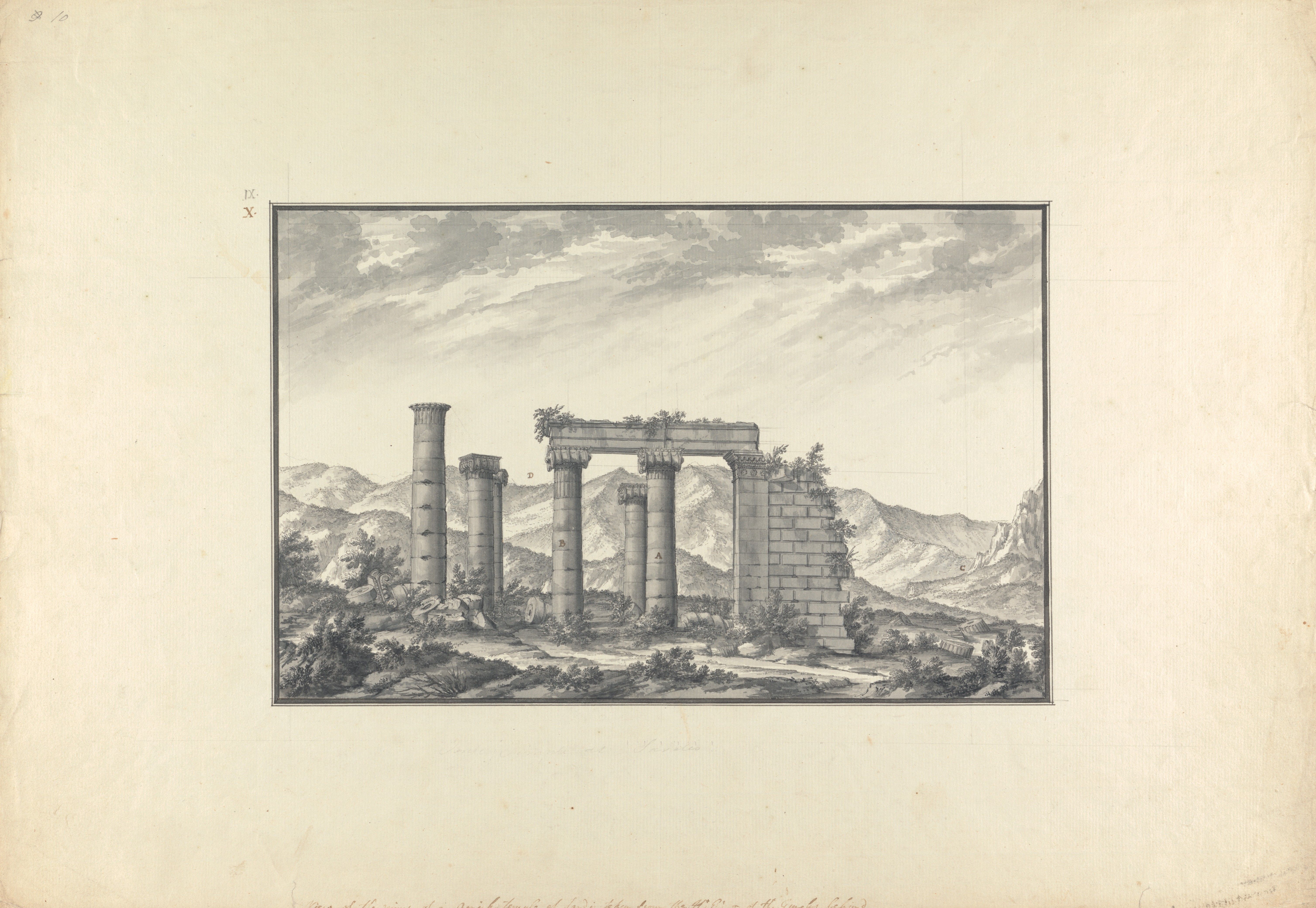
Şek. 1.19
()
-

Şek. 1.21
()
-

Şek. 1.23
()
-

Şek. 1.27
()
-

Şek. 2.180
(Telif hakkı Sart Amerikan Hafriyat Heyeti / Harvard Üniversitesi)
-

Şek. 2.213
(Telif hakkı Sart Amerikan Hafriyat Heyeti / Harvard Üniversitesi)
-

Şek. 2.182
(Telif hakkı Sart Amerikan Hafriyat Heyeti / Harvard Üniversitesi)
-

Şek. 2.228
(Telif hakkı Sart Amerikan Hafriyat Heyeti / Harvard Üniversitesi)
-
Şek. 2.183
(Telif hakkı Sart Amerikan Hafriyat Heyeti / Harvard Üniversitesi)
-

Şek. 2.184
(Telif hakkı Sart Amerikan Hafriyat Heyeti / Harvard Üniversitesi)
-

Şek. 2.185
(Telif hakkı Sart Amerikan Hafriyat Heyeti / Harvard Üniversitesi)
-

Şek. 2.186
(Telif hakkı Sart Amerikan Hafriyat Heyeti / Harvard Üniversitesi)
-

Şek. 2.187
(Telif hakkı Sart Amerikan Hafriyat Heyeti / Harvard Üniversitesi)
-

Şek. 2.188
(Telif hakkı Sart Amerikan Hafriyat Heyeti / Harvard Üniversitesi)
-

Şek. 2.189
(Telif hakkı Sart Amerikan Hafriyat Heyeti / Harvard Üniversitesi)
-

Şek. 2.190
(Telif hakkı Sart Amerikan Hafriyat Heyeti / Harvard Üniversitesi)
-

Şek. 2.191
(Telif hakkı Sart Amerikan Hafriyat Heyeti / Harvard Üniversitesi)
-
Şek. 2.192
(Telif hakkı Sart Amerikan Hafriyat Heyeti / Harvard Üniversitesi)
-

Şek. 2.193
(Telif hakkı Sart Amerikan Hafriyat Heyeti / Harvard Üniversitesi)
-

Şek. 2.194
(Telif hakkı Sart Amerikan Hafriyat Heyeti / Harvard Üniversitesi)
-

Şek. 2.195
(Telif hakkı Sart Amerikan Hafriyat Heyeti / Harvard Üniversitesi)
-

Şek. 2.196
(Telif hakkı Sart Amerikan Hafriyat Heyeti / Harvard Üniversitesi)
-

Şek. 2.235
()
-

Şek. 2.236
()
-

Şek. 2.197
(Telif hakkı Sart Amerikan Hafriyat Heyeti / Harvard Üniversitesi)
-
Şek. 2.199
(Telif hakkı Sart Amerikan Hafriyat Heyeti / Harvard Üniversitesi)
-

Şek. 2.198
(Telif hakkı Sart Amerikan Hafriyat Heyeti / Harvard Üniversitesi)
-

Şek. 2.202
(Telif hakkı Sart Amerikan Hafriyat Heyeti / Harvard Üniversitesi)
-

Şek. 2.223
(Telif hakkı Sart Amerikan Hafriyat Heyeti / Harvard Üniversitesi)
-

Şek. 2.200
(Telif hakkı Sart Amerikan Hafriyat Heyeti / Harvard Üniversitesi)
-

Şek. 2.201
(Telif hakkı Sart Amerikan Hafriyat Heyeti / Harvard Üniversitesi)
-
Şek. 2.220
(Telif hakkı Sart Amerikan Hafriyat Heyeti / Harvard Üniversitesi)
-
Şek. 2.204
(Telif hakkı Sart Amerikan Hafriyat Heyeti / Harvard Üniversitesi)
-
Şek. 2.205
(Telif hakkı Sart Amerikan Hafriyat Heyeti / Harvard Üniversitesi)
-
Şek. 2.206
(Telif hakkı Sart Amerikan Hafriyat Heyeti / Harvard Üniversitesi)
-
Şek. 2.207
(Telif hakkı Sart Amerikan Hafriyat Heyeti / Harvard Üniversitesi)
-
Şek. 2.208
(Telif hakkı Sart Amerikan Hafriyat Heyeti / Harvard Üniversitesi)
-

Şek. 2.209
(Telif hakkı Sart Amerikan Hafriyat Heyeti / Harvard Üniversitesi)
-

Şek. 2.210
(Telif hakkı Sart Amerikan Hafriyat Heyeti / Harvard Üniversitesi)
-

Şek. 2.211
(Telif hakkı Sart Amerikan Hafriyat Heyeti / Harvard Üniversitesi)
-

Şek. 2.212
(Telif hakkı Sart Amerikan Hafriyat Heyeti / Harvard Üniversitesi)
-

Şek. 2.214
(Telif hakkı Sart Amerikan Hafriyat Heyeti / Harvard Üniversitesi)
-
Şek. 2.215
(Telif hakkı Sart Amerikan Hafriyat Heyeti / Harvard Üniversitesi)
-
Şek. 2.216
(Telif hakkı Sart Amerikan Hafriyat Heyeti / Harvard Üniversitesi)
-
Şek. 2.217
(Telif hakkı Sart Amerikan Hafriyat Heyeti / Harvard Üniversitesi)
-
Şek. 2.218
(Telif hakkı Sart Amerikan Hafriyat Heyeti / Harvard Üniversitesi)
-
Şek. 2.219
(Telif hakkı Sart Amerikan Hafriyat Heyeti / Harvard Üniversitesi)
-
Şek. 2.115
(Telif hakkı Sart Amerikan Hafriyat Heyeti / Harvard Üniversitesi)
-
Şek. 2.221
(Telif hakkı Sart Amerikan Hafriyat Heyeti / Harvard Üniversitesi)
-
Şek. 2.222
(Telif hakkı Sart Amerikan Hafriyat Heyeti / Harvard Üniversitesi)
-

Şek. 2.224
(Telif hakkı Sart Amerikan Hafriyat Heyeti / Harvard Üniversitesi)
-

Şek. 2.225
(Telif hakkı Sart Amerikan Hafriyat Heyeti / Harvard Üniversitesi)
-

Şek. 2.226
(Telif hakkı Sart Amerikan Hafriyat Heyeti / Harvard Üniversitesi)
-

Şek. 2.227
(Telif hakkı Sart Amerikan Hafriyat Heyeti / Harvard Üniversitesi)
-

Şek. 2.229
(Telif hakkı Sart Amerikan Hafriyat Heyeti / Harvard Üniversitesi)
-

Şek. 2.230
(Telif hakkı Sart Amerikan Hafriyat Heyeti / Harvard Üniversitesi)
-

Şek. 2.231
(Telif hakkı Sart Amerikan Hafriyat Heyeti / Harvard Üniversitesi)
-

Şek. 2.245
(Telif hakkı Sart Amerikan Hafriyat Heyeti / Harvard Üniversitesi)
-
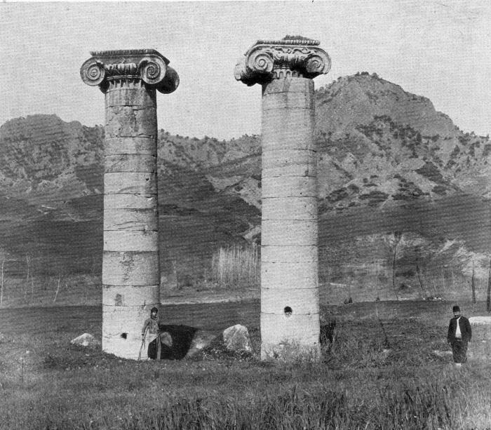
Şek. 1.17
(Howard Crosby Butler Arşiv, Department of Art and Archaeology, Princeton Üniversitesi)
-

Şek. 1.22
()
-

Şek. 1.26
(Yale Center for British Art, Paul Mellon Collection [Folio A N 128 copy 2, drawing opposite plate "Chap.II.Pl.IV" from Antiquities of Ionia by the Society of Dilettanti with annotations by Charles Robert Cockerell, London, 1769-1915])
-

Şek. 2.255
(Telif hakkı Sart Amerikan Hafriyat Heyeti / Harvard Üniversitesi)
-

Şek. 2.264
(Telif hakkı Sart Amerikan Hafriyat Heyeti / Harvard Üniversitesi)
-

Şek. 2.232
()
-

Şek. 2.233
(Telif hakkı Sart Amerikan Hafriyat Heyeti / Harvard Üniversitesi)
-

Şek. 2.234
(Telif hakkı Sart Amerikan Hafriyat Heyeti / Harvard Üniversitesi)
-
Şek. 2.6
(Telif hakkı Sart Amerikan Hafriyat Heyeti / Harvard Üniversitesi)
-
Şek. 2.238
(Telif hakkı Sart Amerikan Hafriyat Heyeti / Harvard Üniversitesi)
-

Şek. 2.239
(Telif hakkı Sart Amerikan Hafriyat Heyeti / Harvard Üniversitesi)
-

Şek. 2.237
(Telif hakkı Sart Amerikan Hafriyat Heyeti / Harvard Üniversitesi)
-
Şek. 2.240
(Telif hakkı Sart Amerikan Hafriyat Heyeti / Harvard Üniversitesi)
-
Şek. 2.241
(Telif hakkı Sart Amerikan Hafriyat Heyeti / Harvard Üniversitesi)
-
Şek. 2.242
(Telif hakkı Sart Amerikan Hafriyat Heyeti / Harvard Üniversitesi)
-
Şek. 2.141
(Telif hakkı Sart Amerikan Hafriyat Heyeti / Harvard Üniversitesi)
-
Şek. 2.4
(Telif hakkı Sart Amerikan Hafriyat Heyeti / Harvard Üniversitesi)
-

Şek. 2.243
(Telif hakkı Sart Amerikan Hafriyat Heyeti / Harvard Üniversitesi)
-

Şek. 2.244
(Telif hakkı Sart Amerikan Hafriyat Heyeti / Harvard Üniversitesi)


Capitals
We have seven capitals (designated by Butler as A through G) in various stages of preservation. There are also four large fragments that belong to the southeast anta capital (placed on the southeast anta by Butler), and two more of the same are in the Metropolitan Museum of Art, New York. Two of the normal Ionic capitals (A and B) are on columns 6 and 7 and are almost intact (Fig. 2.245). Capital A, sitting crooked on column 6, suffered some damage and lost most of its southwest volute at some point in time (Fig. 2.254).124 Capital B is the largest and displays slightly cruder detailing than capital A (Fig. 2.255). Of the five others, capitals C and D are in excellent condition (the former in the Metropolitan Museum of Art since 1922). Capitals E, F, and G have suffered more damage and show extensive ancient repairs. In addition, there are some fifteen to eighteen large fragments (pieces with lesser dimensions not smaller than ca. 30 cm) and as many smaller pieces representing identifiable sections from volutes, bolsters, and echinus eggs.
The largest fragment, designated capital I (in the field, northeast of the temple), is the bolster end of a capital preserved at its full (but partially restored) width of ca. 2.10–2.12 m, with only the tops of opposite volutes but none of the echinus or the profiled edges of the abacus remaining (ca. 2.12 × 1.25 × 0.70 m) (Fig. 2.246). The top of the capital is shorn off completely, leaving no trace of the finished top or the abacus molding, but with a very large corner lewis ca. 0.80 m from the restored front edge (21 × 6 cm long, partial depth 9 cm); we see this on capital G but not A or B, which have central pairs of lewises. The well-preserved, sweeping curve of the pulvinus is decorated with two panels of vertical, round-tipped laurel leaves separated by pairs of cables (panel width 0.32m, cable width 0.12 m, height 0.68–0.70 m), a type seen also on capitals A and C (capitals D, E, and F have plain bolsters). While the incomplete state of this capital fragment does not allow for accurate measurements, the partially restored dimensions indicate that it was one of the larger capitals of the east peristyle, a hypothesis supported by find location and decorative style.
Among the fragments found in the east-porch trenches the largest is a finely molded volute and bolster (ca. 0.60 × 0.50 × 0.35 m; its volute eye 12.8 cm in diameter) found in the 1972 Trench 2 among five smaller fragments. Hanfmann called the larger piece “capital H” and identified as Hellenistic.125 The east porch also produced six medium-sized volute pieces in a 1996 trench and dozens of others in a 2011 trench, some of which join Hanfmann’s capital H.126 Since these capital fragments and other building material from the temple were found in fourth- to fifth-century AD contexts of the east porch, it is natural to assume that they were broken up at that time, although an argument can be made that at least some of this rich material might have been left over from earlier times. Both the mid-second and the fourth to fifth centuries were times when there was intense activity at the east end of the temple, and its columnar elements were refashioned, rebuilt, removed, or vandalized and broken up (some possibly even to feed lime kilns) to accommodate the new purposes (see Ch. 3, pp. 180–181).127
The bottoms of Hellenistic capitals are slightly oval, elongated in the direction of the capital’s main axis, and smoothly finished. All have circular dowel holes in their bottom centers, a common construction detail of the fluted, Hellenistic drums (Figs. 2.258, 2.267). Capitals E and F also each show a pair of small, square side dowels at their bottoms, a Roman era detail and indication that these capitals were reset on new columns during the Roman rebuilding of the temple. Since capitals C, D, and G lack these patently Roman side or corner dowels, one imagines that they were not functionally employed by Roman builders. This idea, first enunciated by N. Cahill, is further underscored by their exceptional quality and refinement, as well as their excellent state of preservation (capital G a possible exception); additionally, they have been found far from any standing column or fallen drum. Unlike capitals E and F, they have no repairs to suggest continued structural use. At the top of the list is the almost-intact capital C, striking in its composition, modeling, and originality. These characteristics identify this exceptional capital as an iconic showpiece from the original temple, never put to practical use in the Roman building and displayed as a “memorial” to the building’s history, perhaps set up inside the new west cella dedicated to Artemis. This beautiful capital continues its iconic vigil today as one of the foremost and striking exhibits in the Greek and Roman galleries of the Metropolitan Museum of Art (Fig. 2.247).128 Capitals D and G, fine but not quite in the same class as capital C, may also be included in this “exhibition group,” mainly because their bottoms lack the small, square side dowels typical of Roman usage that we see in capitals E and F.129 The presence of Roman era standard lewises on these capitals (one pair on capitals C and D; two pairs on capital E; and triplets on capitals F and G), on the other hand, can be explained by the need to move these capitals from their original high positions and transfer them to their new display position, wherever that might have been. Although the evidence is not clinching, it is strong enough to conclude that the smaller capitals, once functional inside the cella, found no structural use during the Roman construction of the temple.
Another construction detail that might shed some light on the positioning of these capitals is the presence of round corner dowel holes on top of capitals E and F (probably positioned on all four corners, some with pouring channels; see Figs. 2.266, 2.268) while capitals C, D, and G have no round dowels on top (Fig. 2.259). This top detail suggests that capitals E and F were originally attached to stone architraves. If they were used inside the cella, they could have carried stone architraves spanning their long, east–west direction, which is the short span of the cella colonnade; double wooden beams or trusses carried by these architraves could have crossed the long, north–south span (ca. 6.70 m)—a typical structural arrangement for a cella roof. Yet, the “medium” size of E and F could have discouraged their use upon the smaller columns of the cella where “smaller” capitals (C, D, and G, with no round, Hellenistic era top dowel holes) would have been more appropriate. In antis columns of the east porch would appear, at the first glance, to be a better position for them although the immense 8.30–8.40 m center-to-center span reconstructed for this position (ca. 5.80 m clear span) is also not ideal for stone architraves, as signaled by their round top dowels. Likewise, does the absence of round dowels on the tops of capitals C, D, and G mean that they did not carry stone architraves (if so, would their possible use inside the Hellenistic cella be compromised because stone architraves could be expected for the short, east–west position?). Inconsistences in the use of such construction features are fairly common in the temple; as is often the case for these capitals, the diagnostic details represented by our statistical samples are too small to serve as proof.
Capitals C–G display a lifting device called a Carian-Ionian lewis, whose use is restricted to the Hellenistic era (the system went out of use by the second century BC, see pp. 29–31 above; Figs. 2.265, 2.268), which reliably identifies these capitals with the original, Hellenistic phase of the temple. Lifting sockets of the Carian lewises are positioned at the centers of the capital tops. These capitals also have two or more standard Roman lewises (typically arranged in matching pairs, but positioned symmetrically on the axes of the capital with less exactitude, some off-center of an axis by ca. 10–15 cm) which must have been carved later, signifying Roman period rebuilding or relocation. As is expected, the two in situ Roman capitals, A and B, each display only a pair of standard lewis holes centered on their top surfaces (Fig. 2.253).
Due to their delicate design and decoration, the capitals were more vulnerable to damage during their long history. One of the major causes of breakage (except natural causes, such as earthquakes) was the Roman period of rebuilding activity when many capitals were removed, re-lifted, and repositioned on new or re-erected columns. These damages, often affecting the delicate volutes and ornament, were repaired with new pieces that fit precisely. One can see substantial repairs on the inner and outer volutes of capital F, parts of them entirely rebuilt with iron pins still in place (Fig. 2.248). Likewise, the volutes and parts of the lotus-and-palmette ornament between the volute and the echinus eggs of capital E received major repairs (Fig. 2.249). The process underlines not only the dangers of rebuilding and reuse but also the determination to make the damage good again through expert methods of repair. Less delicate but probably just as effective was the employment of clamps across developing cracks, as we see on capitals F and E.
The upper surfaces of most of our capitals, especially capitals C–F (all Hellenistic originals), are left rather rough, finished in medium or rough point chisel.130 In the case of capitals C and D there is also ca. 1–2 cm difference in level for about one-third of the top surface (Fig. 2.259). Butler was concerned that such rough tops would make poor surfaces for heavy architraves and suggested that molten lead was poured over the top of capital C to create a smooth bed, but this is unlikely.131 Simple strips or shims of lead, however, were certainly used in the joint between the torus and scotia of the base of column 13 (Fig. 2.222) as well as between the second and third courses of the northeast anta pier base and the course above, and probably also in the same joint along the north face of the wall (the joint at ca. 2–3 mm is much wider than the normal, razor-thin wall joints; see pp. 41–43 above). Still, capitals C, D, and G—the group of small capitals with rough tops and no top dowels but with lewis holes—indicate evidence for lifting but not necessarily reuse.
Classification of Capitals According to Size
The seven better-preserved capitals of the temple are compared and grouped according to size and the results given in Table 2.4 (p. 135). The relevant dimensions used to register capital size are the following: (a) width at abacus top (front); (b) width at abacus top (side); (c) maximum volute-to-volute width; (d) volute eye-to-eye width; (e) bolster/pulvinus width (side); (f) height (abacus top to impost bottom); (g) diameter of volute eye. Another important dimension, the diameter(s) of capital bottom (impost) is not included since this area is never a true circle but an oval (measurements are given in individual descriptions of capitals). Direct measurements were taken as often as possible; reconstructed dimensions, if reliable, are given in parenthesis; if reasonable variance exists, the range is given. It is important to note that capitals A and B, intact on their columns, were measured directly and reliably for the first time because of the scaffolding erected around columns 6 and 7 in 1992 (Figs. 2.254, 2.255). This also gave us the chance to make some measured pencil sketches of the details of the capitals A and B (Figs. 2.250, 2.251, 2.252).
The largest capital with a substantial margin over the others in overall size and dimensions of its parts is B (abacus 2.22 × 2.11 m; Fig. 2.255). Next is capital A, roughly 0.10 m smaller than B at its abacus and 0.19–0.20 m at the maximum volute width (abacus 2.10 × 2.01 m; Fig. 2.254). Capitals E and F are quite close to each other in proportions and size, and substantially smaller than A and B (Figs. 2.264, 2.269). Capital E, which is the better preserved one, is the same size or only a few centimeters larger than capital F, whose abacus and volute dimensions are based on partial reconstruction (capital E abacus 1.94 × 1.69 m; capital F abacus frontal width, restored 1.92–1.94 m). With dimensions conforming exactly, or in a few cases within centimeters of each other, capitals C (Figs. 2.256, 2.257), D (Figs. 2.260, 2.262, 2.279), and G (Figs. 2.270, 2.280) are a group roughly one-eighth smaller than capitals E and F; and one-fifth smaller than capital B. As the best-preserved example of this group on site, the dimensions of capital D can be taken as representative and compared to capital C (capital D abacus 1.76 × 1.67 m; capital C abacus 1.74 × 1.67 m; capital G abacus restored 1.76 × 1.67 m).
On the basis of size alone (regardless of date or origin) it appears that the seven preserved or partially preserved capitals of the temple represent three groups assignable to specific positions or columns, at least in theory. Roman capitals A and B, already in their original positions on the east peristyle, belong to the larger size. Since the remaining base plinths of the north and south colonnades (column 15 of the north colonnade, column 20 of the south colonnade, and the plinth of column 18: the one remaining column of the south colonnade) are all practically the same size as the plinths of the east peristyle columns, we can surmise that all the finished peripteral Roman era columns received capitals of the first (large) group, probably fairly close in size and detail to capital B or A. At least in the case of columns 6 and 7, a fair amount of variation in capital size was tolerated between columns of virtually the same size and next to each other (there is a difference in abacus size of about 10–11 cm between the capitals of columns 6 and 7 although their top shaft diameters vary only by 2 cm: 1.76 m for column 6, which received the smaller capital A, and 1.78 m for column 7, which received the larger capital B). We have provisionally identified the capital for column 1 or 2 to be the fragment I (about one-quarter of the top of the pulvinus side preserved) fallen next to these columns. From available measurements, this fragment belongs to a large capital. We have no other assignable capitals identified for the peripteral colonnades, except perhaps the large volute fragment found in 1972 (capital H) that might have belonged to one of the in antis columns of the east porch where it was found (volute eye diameter 12.8 cm, second only in size to capital B; see above).132
Capitals E and F represent the middle-size group and must belong to the original Hellenistic temple because of their Carian lewises. Found at the southeast end of the temple, capital E could have belonged originally to one of the in antis columns of the east porch. If these in antis columns were removed during the Roman reconstruction (not a certainty), they could have been repositioned on column 13, the southeast outer-corner column of the pronaos porch, as indicated by the top setting lines for a corner architrave (see below). Capital F was found outside the northeast angle of the temple and could have been assigned a place on column 10, the northeast outer corner of the pronaos porch, in Roman times because the weathering pattern of its top is right for the exposed-corner position. The medium size of these columns was appropriate for reuse in these locations since the porch columns were a size between the larger columns of the peristyle and the smaller cella interior columns. Another reason for favoring capitals E and F for the porch positions is their unusually elongated abacuses, which would have reduced the span of their major long axes, unlike the rest of the capitals, whose abacuses are more square in proportion. If the drawing made in 1750 by Robert Wood’s draftsman, Giovanni Battista Borra, is right in showing the volutes of the capitals of the three visible columns of the east pronaos porch facing east–west like the capitals of the east colonnade (and not special corner Ionic capitals for columns 10 and 13, as one would have expected), the elongated tops of the abacuses of columns 13 and 10 would have helped to reduce the exceptionally long spans of columns 10 to 11 and 12 to 13 (ca. 6.64–6.67 m on-axis span, as opposed to the ca. 4.97–4.99 m on-axis spans of 16 to 10 or 17 to 13; Figs. 1.18, 1.19).133
The three well-preserved capitals C, D, and G, almost identical in dimensions, belong to the small group. Their original positions must have been the interior of the cella, which required smaller capitals because, rising from the higher level of the cella (ca. 1.60–1.70 m higher), these columns were shorter. In their Roman incarnation these smaller capitals would have been appropriate: capital D (found southeast of the temple) in the middle position of the east pronaos porch or on columns 11 and 12; and capitals C and G (found on the southwest and northwest sides of the temple) in positions 53 or 54 respectively, of the west pronaos. As discussed above, however, these capitals (especially C) are believed to have been set aside as display models.
Another noteworthy, size-related feature of our capitals is the varying number of eggs decorating their front and side abacuses (all counting the corner eggs): capital B, 12 × 12; capitals A and E, 12 × 11; and capitals C and D, 14 × 13; capital G, only preserved back, 13. It is interesting that the larger capitals have fewer, larger eggs (about one-quarter larger), smaller capitals have more, smaller eggs (original, smaller capitals displaying greater labor). This apparent incongruity probably reflects their dates and origins: the constituent elements in the larger Roman examples (capitals A and B) are larger, fewer, and simpler, which is consistent with the Roman tendency to simplify details and economize work compared to the finer detailing of Hellenistic period.
Capitals A and B
Among the temple’s capitals, A and B—preserved in situ on columns 6 and 7, respectively—are the only ones with standard-type, rectangular lewises as elements for lifting that are associated with the Roman era (Fig. 2.253). With one pair per capital, the lewis holes are centrally and symmetrically placed (capital A: 26 × 11.5 × 19 cm and 18 × 10 × 19 cm; capital B: 24 × 12 × 20 cm and 22 × 11.5 × 19 cm); those of capital A are placed parallel to the long axis of the capital, and those of B are placed parallel to the short axis, or the pulvinus side of the capital. There are no dowel holes, setting lines, or marks for architraves, even though we know that at least these two columns carried an architrave (recovered intact, see below). Their top surfaces are finished relatively smooth in point chisel. Capitals A and B also demonstrate different detailing solutions for the connection between the capital and the column top drum (Figs. 2.254, 2.255). In the former we have a rare application: the uppermost drum of the column and the capital are monolithic. This drum is carved with the usual crowning astragal (bead-and-reel) and apophyge above a short portion of fluting tops (ca. 18 cm high) that joins the unfluted drum below it. All other capitals exhibit normal joints between the top drum of the shaft and the capital impost. In normal detailing of capitals, as in capital B, the volute eye falls 12 cm outside of the column neck and 8 cm higher than the column top. The smaller size and unusual design of capital A creates an exceptionally snug fit; the volute eye is only 3 cm outside the column neck and 2 cm higher than the column top.
Capital C
The Carian lewis of capital C, now in the Metropolitan Museum, is only known from a drawing (Sardis 2.1, atlas, pl. XI; Fig. 2.257), since the middle portion of this capital was carved out in modern times, probably to make it lighter for transport from Sardis to New York in 1922 (Figs. 2.247, 2.256).134 The lifting socket of the Carian lewis was positioned exactly at the center of the capital top (10 × 3.8 × 23 cm; the square socket was 32 × 29 × 23 cm). A pair of standard lewises (14 × 6 × 14 cm) are centrally positioned to face the front and back of the capital, but situated unevenly in relation to the sides; the right one (facing front) is 18 cm closer to the edge than the other. There is a single, small square dowel hole at the back left corner (6 × 4 × 6 cm). The underside of this capital has a single round dowel in the center bottom, there are no square side dowels, suggesting that it was not functional during the Roman period.
Capital D
The underside of capital D (1.56 × 1.52 m in diameter) has a single Hellenistic round dowel viewed during its 2017 moving (Fig. 2.258); there are no Roman era square side dowels. Like capital C it might not have been used during the Roman period. The top surface (ca. 1.76 × 1.67 m) is finished in rough point chisel, with the right side (faced from the front) one-third higher than the left by 2–3 cm, with a slightly smoother band running across its middle (Fig. 2.259). The lifting socket of the Carian lewis is positioned in the center of the capital top (8.5 × 3.6 × 25 cm; the large, square portion is 29 × 27 × 26 cm with deep gouging around its sides. A pair of standard Roman lewis holes of different size are set on either side of the Carian lewis, offset from the center by 8–9 cm (18 × 8 × 18 cm; 13.5 × 7 × 15 cm; distance to the edge is 41 cm on the left and 24 cm on the right). A single, rectangular dowel hole (7 × 7 × 5.5 cm) is on the back-right corner. The abacus measures 1.74 × 1.67 m, with twelve eggs on the front and back, eleven along the sides (Fig. 2.261). The front and back, as well as both pulvinus sides, are well preserved and missing only small portions of the volute bottoms (Figs. 2.260, 2.261). The refinement of the small, elongated eggs of the egg-and-dart and the delicate “bell-flowers” (Butler’s term) at the ends of the curling acanthus ornament of the front echinus are noteworthy (Figs. 2.262, 2.263).
Capital E
The underside of this capital has an oval resting surface (1.74 × 1.65 m), a Hellenistic round dowel in the middle, and a pair of Roman square side dowels. The back and right sides of the top are broken away across a diagonal line from the right front to the left back (Fig. 2.265). A pair of poorly preserved clamp cuttings at front right represent a Roman era repair. The top surface displays a fairly coarse finish in pointed chisel. Based on restored distances, a Carian lewis occupies the center. Its lifting socket (13 × 4.5 × 28 cm) is only 4-5 cm off-center from the short axis of the capital; its larger, square portion is 28 × 28 cm and has sides that are cut back unevenly 6–9 cm. There are two pairs of standard Roman lewis holes. The first pair is placed on the capital’s long axis, symmetrical on either side of the Carian lewis (the left is 15 × 10 × 14.5 cm; the right is preserved only at its bottom). The second pair, probably representing a later lifting operation (i.e., after the capital was damaged), is located in front and back of the Carian lewis, the back one cut deeply into the broken back of the capital (the front is 15 × 8.5 × 17 cm; the back is 14.5 × 6 cm, its depth indeterminate due to the break). Round dowel holes occupy the preserved left front and back corners (ca. 30 × 32 cm from the edges of the abacus, 7 cm in diameter and 6 cm deep); the front dowel has two pouring channels, (Fig. 2.266) while the back one, not well preserved, does not appear to have any. These dowels may represent original, Hellenistic use of the capital, possibly inside the cella to support a stone architrave in the short east–west direction (see above and as reconstructed in Fig. 4.14).
The capital top also displays setting lines for an architrave, ca. 13 cm from the front and left edges, and an L-shaped one on the front-left corner, probably belonging to the Roman re-setting of the original Hellenistic capital (Fig. 2.265). As observed by Cahill, “the capital must have been exposed to weather for a significant period of time . . . with no roof (to protect it),” since the edges of the capital top are eroded.135 Based on the position of the corner setting for an architrave, capital E must belong to column 13, the southeast corner column of the east pronaos porch. Similar round corner dowels are found on the tops of capital F but not C, D, or G, nor are they found on the Roman capitals A and B, nor on the undersides of any Roman architraves.
Top Column Drum under Capital E
The top drum upon which Butler placed capital E (the drum and capital were found together and placed on foundation 22 in 1912) is 0.58 m high and has a crown molding of bead-and-reel, a fillet, and a neck apophyge that eases into the encircling band of flute tops (ca. 24–28 cm high, 8 cm deep) over a coarse, unfinished bottom band (24 cm high; Fig. 2.264). As seen on column 7 and other peristyle columns in early travelers’ sketches, this appears to have been the standard Roman top-of-column detail (sometimes the top two drums are fluted); the unfinished flutes, probably carved on the ground, set a template for the rest to be carved in situ (see pp. 95–97 and pp. 114–116 above). When capital E was lifted in 2017, we found that the usual two small, square side dowel holes and a pair of standard lewis holes on the top surface of the drum were unremarkable, but a Carian lewis was an unexpected and baffling feature for Roman period construction. Quoting Cahill:
On its [i.e., the drum’s] underside it bears anathyrosis and two Roman square dowels but no central round dowel. The Carian lewis would seem to mark it as a Hellenistic block, but the unfinished [bottom] band and lack of a round dowel on the underside are difficult to reconcile with this. The resolution could be that the block [was] a Hellenistic capital recut in the Roman period into an upper drum; they simply did not cut away the original Carian lewis but did trim off the bottom [and that is why there is no Hellenistic round dowel].136
Capital F
The bottom surface of the smooth underside is 1.68 × 1.72 m; it has one round dowel hole in the middle (9 cm in diameter, 9 cm deep; Fig. 2.267). Symmetrically arranged about this dowel are a pair of square dowel holes (each 4 × 4 cm) recognized as additions and indicating Roman use. This capital was found at the northeast corner of the temple, “under the debris above ground,” as described by Butler.137 Though we cannot be sure when it fell, Cahill notes that the extensive rainwater erosion on its broken surfaces suggests that it was exposed to the elements longer than capital E.
The top of the capital is fairly well preserved, the damage contained mainly to the front and left sides (Fig. 2.268). The top surface is finished in medium-coarse point chisel and has a large crack in the middle, running front to back. Three bar-clamp holes, a pair at front and back (ca. 12 cm from the edge) and one roughly in the middle (0.23 m, 0.23 m and 0.31 m long, respectively) provide evidence for an ancient repair. The Carian lewis has a lifting socket centered on the capital top (3.5 × 11 × 23 cm), and the larger rectangular socket (28 × 25 × 23 cm) widens at the top to a substantial 39 × 35 cm. There is a set of three standard Roman lewises, two in front on either side of the Carian lewis and one behind it, outlining a centrally positioned lifting triangle (15 × 9 × 18 cm on the left; 14 × 7 × 15 cm on the right and 19 × 8 × 22 cm on the back). In addition to this set there are two Roman lewis holes on the long axis of the capital located on either side of the Carian lewis, possibly representing a second lifting during the Roman era. The right-facing lewis is offset by ca. 10 cm, located at the edge of the Carian lewis and very close to the crack (the right lewis hole is 10 cm from the lifting center of the Carian lewis and the capital; the left one is 30 cm from the center). This appears to be an empirical application of construction statics, the short moment arm on the right—close to the crack—minimizes the stress on the stone (i.e., the rotational moment about the crack). Four round dowel holes with pouring channels are located at the four corners of the capital top (18–19 cm from the edge at the front and 28–29 cm at the back; holes are 7 cm in diameter and 6 cm deep); comparable to the circular top dowels of capital E, they are judged to be Hellenistic features that signal the use of architraves.
The back side of the capital displays partially preserved volutes (Fig. 2.269); the outer edge of the left one is repaired neatly with a dutchman and a pair of iron pins in situ; the damaged pulvinus channel behind this volute shows an ancient repair by a hook clamp, 19 cm long. Likewise, the right volute has an ancient repair at bottom with a smoothly cut dutchman and two iron pins. Cuttings in the centers of both volute eyes indicate the application of ancient ornamentation. The front side of the capital is poorly preserved except for a central rosette above the echinus and the palimpsest of acanthus tendrils. The egg-and-dart of the abacus is entirely missing.
This medium-sized capital could have belonged to one of the porch columns, either 10 or 16. The noticeable weathering along the unprotected front and right sides of the capital suggests that it was on column 10, “since the top of 16 was protected until at least 1750,”138 (the capital on column 16 would have been protected better than that on column 10 by its two-way architrave, as seen in the Borra illustration, Figs. 1.18, 1.19).
Capital G
Capital G was found “well beyond the northwest angle of the peristyle.”139 Its smooth underside has one central, Hellenistic round dowel and no square side dowels, suggesting that this capital, too, might not have been reused in the Roman period (or, are we suggesting too many “display capitals”?). The front is completely shorn off, leaving some three-quarters of the top, both volutes, echinus, and the central rosette of the back almost intact (Figs. 2.270, 2.280, 2.282). The abacus can be reconstructed at 1.75 × 1.66 m with eleven eggs on the well-preserved back side. Finished in fine point chisel, the upper surface of the capital is remarkably smoother and less cluttered than any other. The lifting socket of the Carian lewis is centrally placed (10.5 × 3.6 × 19 cm); the large rectangular socket (29 × 27 × 19 cm), unlike those of other capitals, shows no apparent widening or gouging of its sides. There are two standard Roman lewis holes on the right side of the Carian lewis (viewed from front), both ca. 24 cm from the abacus edge; the back right corner one is 11 × 5.5 × 13 cm; the other, front right corner one is mostly gone, visible only as scar of its bottom. Although balanced on the long axis of the capital, these two hardly make a lifting pair since they are on the same side of the short axis. A third lewis hole on the left side is centered on the capital’s long axis (15 × 6.5 × 18 cm; ca. 14–15 cm from the Carian lewis), and working together with the previous two, it could make a well-balanced lifting triangle centered on the lifting socket of the Carian lewis. The question is why utilize triple lewis sets when a well-centered pair would do? Unlike capitals E and F, the top of this capital is free of other construction features such as round (or square) dowel holes or setting lines. The standard lewises indicate it was lifted and moved in the Roman period.
Stylistic Considerations of Capitals
Although this is a chapter devoted to physical descriptions (with some minimal interpretations), stylistic considerations of the capitals naturally include close, detailed descriptions of physical features. And in this way, we keep all discussions about the capitals together. All except one of the capitals are surmounted by abaci of open egg-and-dart rows (all darts are of the pointed, bar type) with corner eggs decorated by inverted palmettes. The only known capital to employ a plain fillet terminating the abacus, arrow-shaped darts, and plain corner eggs is capital B on column 7 (Figs. 2.272, 2.273). The echinus decoration of all capitals, especially capital C—with well-rounded and deeply set eggs inside their shell-like casings and separated by elegant, thin darts—display a sculpted plasticity that invites comparison to the superbly turned out egg-and-dart molding of the single, preserved Hellenistic anta capital of the temple (Fig. 2.275; compare Fig. 2.293). The eggs of all echinuses are plain except for those of capital C, which are decorated with richly carved inverted palmettes growing from egg casings that are converted into delicate, ribbed acanthus calyxes and scrolls (Figs. 2.256, 2.274). The tongues/darts between the echinus eggs are also carved as pairs of slender stalks terminating in inverted buds and triple-leaf palmettes—“which take the place of ordinary sharp rims (‘tongues’ or darts) flanking the eggs”—unique details in the vocabulary of Ionic capitals (Fig. 2.275).140 The volutes have deep, rounded channels and make three turns around a flat, round eye. On capitals A, B, E, and F the centers of the eyes are carved with small, rectangular holes, probably to anchor some kind of metal ornament; this is confirmed by the lead “oozing” out of the volute eye on capital B (Fig. 2.276).
On capitals D and G, the centers of the volute eyes are marked by thin, vertical setting lines that cross the entire width of the circular eye, occasionally with faint erasures (Figs. 2.277, 2.278). In addition to the crossing center lines of the front (exterior) left volute of capital D, there are two additional vertical lines to the right and left of the center; the center of the right volute is defined by a pair of vertical lines on either side of the center (2.5 mm apart). The back (interior) left volute eye also has two additional vertical lines (1.2 cm apart) on either side of the center cross; the right eye has no horizontal line to define the center crossing; a vertical line passes through the center point, with an additional vertical line 7 mm to its right. Only the back (interior) volute eyes of capital G are preserved. The left eye has only one vertical line passing through the center; the right one is defined by a pair crossing through the center.
The volutes of capitals C, D, and G are connected by a gracefully dipping fillet (sometimes called a listel) that leaves a large “channel” above for ornament (Figs. 2.270, 2.274, 2.279, 2.280); on capitals E and B there is no fillet connecting the volutes and the top of the echinus with the strongly projecting triple egg-and-tongue, which is invisible from below. It is left quite rough, and in the case of capital E it appears unfinished (Fig. 2.264). The profiles of the “reed” that connect the volutes (seen from the front or the back) directly under the abacus vary slightly. In capitals A, C, E, and F, this cable-like element is well rounded; in capitals B and G it has a flatter profile and meets the abacus projection above almost at a right angle (cf. profiles in B, Fig. 2.287, bottom; and A, Fig. 2.286, bottom). The concave curve of the volute channel directly above the echinus (egg-and-dart) is also shallower for B and G. The volute channel of each capital is decorated on the front by a pair of undulating, ribbed acanthus stalks and tendrils ending in a delicate, upturned half-palmette on either side of a six-petal rosette (as seen restored on capital C; Fig. 2.274); this leafy motif grows out of a pair of shorter acanthus stalks that terminate in delicately curling leaflets, as preserved on capital E and restored on capital A (Figs. 2.264, 2.286); the back side of the capitals are simpler with only a six-petal central rosette and no acanthus stalk.141 The rosettes of capitals D and G are identical (Figs. 2.260, 2.270), while capital C has an exceptionally elaborate rosette with doubled petals; the rest show minor variations on the basic model. The side eggs of the echinus are partially covered by single-sided palmettes, hanging downward from a stalk growing from the corner of the volute. In some (capitals D and G), the tips of the palmette leaves are pointed, lying flat on the egg of the echinus (see Figs. 2.281, 2.282); on others (capitals A, B, and C) they curl and turn upward (Figs. 2.254, 2.255, 2.256). Capitals C and D are also the only extant ones where the corner stalk grows from a delicate calyx or “bud” with scalloped petals; in others, this calyx is left plain (Figs. 2.256, 2.281).
Butler observed that “one of the most interesting features [of capital C] is the marked inward slant of the volutes from top to bottom, which gives . . . firmness and compactness in design, and undoubtedly added much to the effect of the volute scrolls when seen from below” (Fig. 2.284).142 The same sentiment was echoed in 1922 by architect Lansing “Denny” C. Holden, Jr., a member of the Butler team and one of the draftsmen of these capitals, that the ornament of the volute band and the palmettes of the echinus appear visually connected, “creating a unified mass . . . not only from close up but from a distance”143—and to this we will add from below, as they were normally viewed.
The pulvinus sides of all capitals are articulated by five pairs of reeds or astragal moldings that create four channels, two at each end that define the volutes and three in the middle. The bottoms of these channels are decorated with palmettes in all but capital F. On capitals C and A (as well as on some capital fragments), the middle two channels also display overlapping vertical leaves (or “scales”) pointing downward, similar to the laurel-leaf torus decorations of some of the bases (11, 12, 16, and 17; A: Figs. 2.283, 2.285, 2.286; C: Fig. 2.284); in others this area is left plain (B: Figs. 2.272, 2.287; D: Fig. 2.279; G: Fig. 2.280; E: Fig. 2.290). A comparable version with a slightly pointed laurel-leaf motif is also seen on the large capital fragment (I) left in the field to the northeast of columns 1 and 2. Another subtle variation in design is the gentleness of the curve with which the pulvinus meets the abacus, visible when looking at the side of capital. In capitals A, D, and C the sweep of the pulvinus has a uniformly gentle, upward curve (A: Figs. 2.286, bottom, 2.289; D: Fig. 2.279); in capitals B, E, and G the upper portion of the pulvinus meets the abacus in a steep, almost straight line, the curve beginning only halfway down the volute (B: Figs. 2.272, 2.287, bottom; E: Fig. 2.290; G: Fig. 2.280).
As apparent from the discussion above, all the capitals of the temple—Hellenistic or Roman—share basic stylistic similarities and conventions with minor variations. With delicately curving and ribbed acanthus stalks, bunched leaflets growing out of calyxes and buds, or tulip-like flowers growing at the ends of gently waving stems, sketchy and delicate but sharp and linear, they belong to a generally recognizable decorative and stylistic family of Hellenistic ornament from Asia Minor.144 However, it is possible to assign them to several subgroups based on size (see above), type of ornament, stylistic conventions, and to a lesser extent, degree of refinement in workmanship and modeling. One understands that stylistic differences, such as they are, represent normal and creative variations among the different craftsmen who made them, except for the more substantial differences of Roman era capitals A and B. Among the Hellenistic capitals, capital C can be singled out from the rest not only because it displays the finest modeling, but also it has unique and sophisticated features, such as the rich and unusual decoration of the echinus (eggs decorated with inverted palmettes, egg casings developed as acanthus stalks and calyxes) and the subtle, inward curve of its volutes. Capitals D and G are close comparisons in structural form as well as artistic delicacy and richness of ornament. Even the two patently Roman capitals, A and B, vary notably in quality. Capital B, on column 7, represents the greatest deviation from the original models, as it is generally sketchier and cruder than the others. Its volutes and volute channels are flatter. Its upward pulvinus curve is steeper while its mate, capital A, displays a gentler curve, probably in imitation of capital C. Capital B is also the only example with a fillet that crowns a coarser rendition of the egg-and-dart abacus (and not egg-and-tongue like all others). Still, its echinus has sculpted, rounded, and deeply encased eggs in the distinctive style of the Sardis capitals, rather than the delicate, pointed, and rather shallow egg-and-tongue molding typical of late Hellenistic capitals or ornament of Asia Minor in general, such as the near-contemporary work at the Belevi Tomb monument (Fig. 2.291). The elegance and firmness of the volutes of capitals A (Fig. 2.254) and B (Fig. 2.255), enhanced in our detailed views, are hard to match not only among other Roman examples, but even Hellenistic ones, as seen in the capitals of the Temple of Artemis in Magnesia (Fig. 2.292). Understandably, capital B (the largest) was the only capital believed by Butler to be a Roman copy, “set up a second time on a shaft of later date in connexion with extensive repairs at this end of the temple.”145
Lansing (Denny) Holden, who had measured and studied the capitals of the temple during a wartime campaign at Sardis in 1922, described them later as “the most beautiful things I have ever seen.” Many artists and scholars would have agreed with Denny, an architecture student of Butler at Princeton, a flying ace and avowed risk taker who was the first person to hoist up himself the full height of column 7 in 1922 using a bosun’s chair and record it with astonishing accuracy.146 Singly viewed, all capitals of the temple are beautiful and subtly varied; their aesthetic effect as a group lined up in a row must have been impressive (four have been lined up as a group in 2017 in a protective shed [Fig. 2.271] and described by the excavation members, separately, as looking “regal”). It is understandable that, faced with such an exquisite array of Ionic capitals, Roman sculptors and craftsmen had little need and probably no desire to go elsewhere for models. It might be that the late-Hellenistic version of the typical Ionic capital widely used in Asia Minor even under the empire held little appeal; it tends to be more linear with taut, shallow volutes, shallow and pointed egg-and-tongues like fine china, as opposed to the rounded, substantive plasticity of the Sardis capitals. The original capitals of the temple provided an impressive set of prototypes to imitate and emulate. Naturally, the credit for creativity and inventiveness must go to the Hellenistic masters who fashioned the originals, but even the copies created by their Roman followers are distinctive.
The Sardis capitals were part of a group of Ionic capitals (with those of Delos, Halicarnassus, Priene, and Didyma) studied for stylistic and structural similarities by M. Mărgineanu-Cãrstoiu and A. Sebe. Following the internal and external characteristics of their volute spirals, and based on the hypothetical geometry of a central pentagon, the authors demonstrated certain basic controlling relationships and correlations among the examples (the mathematics involved in this analysis is not for the faint hearted). While deemed to be a part of the established Ionic stylistic order of the group, the Sardis capital analyzed (capital C) is shown to be its most-independent, least-conforming member; perhaps this explains its visual allure as the least-mechanical, most-creative and beautiful member of the group.147
Anta Capitals
Six large fragments of an anta capital were found by Butler’s team very near the southeast anta pier and judged to belong to this position. Four of these fragments are now placed on site on the southwest anta, at or close to their approximate positions (Fig. 2.296); a fifth, smaller fragment (ca. 0.80 × 0.80 × 0.50 m) has only the top molding with a few segments of egg-and-bar, bead-and-reel, and part of the projecting fascia; it is located east of the temple among other column fragments of the east peristyle. Two other pieces are at the Metropolitan Museum of Art in New York (inv. no. 26.59.12a, b). Although none of these fragments match, the remaining pieces are complete enough to allow for a reliable restoration of this anta capital.148
The anta capital is composed of two parts. The upper half is a cornice with a strongly projecting fillet and fascia over a bed molding of large egg-and-tongue and bead-and-reel (total height: 52 cm; bed molding: ca. 27–28 cm; eggs: 19 × 16 cm; center-to-center distance: 27.6–27 cm; Fig. 2.293). The bottom element is a flat frieze of thinly modeled laurel wreaths, four on each side of the anta pier, and each with a rosette in the center and crowned by a delicate bead-and-reel under a lesbian cyma (total height: 63.4 cm; flat frieze height: 41.6 cm; cyma reversa crown molding: 16.4–16.6 cm; diameter of wreaths: 36–37 cm; Fig. 2.294, 2.295). The egg-and-tongue and bead-and-reel of the cornice ovolo is deeply carved and fully rounded, the former comparable in style to the echinus of the regular capitals (including the specific decorative motif of articulating the corner egg of the cornice with an inverted palmette), and to some extent, the egg-and-dart molding of the Hadrianic east door jambs (see pp. 167–174). The contrast between the boldness of its ovolo cornice and its delicate frieze is noteworthy. Compared to many contemporary Hellenistic examples of pier and anta capitals (e.g., from Magnesia, Labraunda, Priene, Samos, and Samothrace), which are characterized by their trapezoidal shape, elegant but rich, fussy, and layered moldings, the flat and sparse simplicity of the Sardis anta capital appears unusual and sophisticated—and stylistically enigmatic. While the deeply carved eggs of the cornice can be compared to Hadrianic ornament (at least to a point), the shallow and delicate frieze definitely cannot. As noted by Butler, who appreciated the stylistic superiority of their ornament over their peers, these are “the most interesting and beautiful anta-caps yet discovered.”149
Two cornice pieces are placed on the outer (south) face of the southeast anta pier, one being the southeast corner piece; two on the inner (north) side belong to the frieze, including the piece for the L-shaped inner reveal of the anta pier (Figs. 2.296, 2.297). This frieze piece is carved as a monolith with its westward continuation on the anta as an unornamented wall block with narrow, drafted edges (Fig. 2.294). The tops of all anta capital fragments are finished in fine or medium point chisel, their top surfaces prepared to receive upper elements—either the anta cornice above the frieze, a wall architrave on the outer (north) side, or a regular architrave that must have spanned the southeast and northeast anta piers and the original in antis columns of the east pronaos porch. The edges of some of these blocks are discernible as slightly raised impressions on the top surfaces of the anta capital (Figs. 2.296, 2.297). Interestingly, the tops of all blocks (where preserved) display large, square dowel holes with pour channels (ca. 6–7 × 6.7 cm, with 14–15 cm long pour channels) and standard lewis holes (10.5 × 5.5 × 7.2 cm; 15 × 6.5 × 10.2 cm). The southeast corner cornice (ca. 1.19 × 0.95 m; 0.53 m in thickness; Fig. 2.298) has a finished western edge with anathyrosis and a large, deep cutting for half of a hook clamp (14 × 10 × 10 cm), as does one of the two cornice blocks at the Metropolitan Museum of Art. The second cornice piece placed west of the southeast corner has a rough, raised band 33 cm wide along its outer edge (1.06 × 1.02 m) and a dovetail clamp along its broken west side inside a 13–14 cm-deep cutting; it probably marks a late repair for a crack (Fig. 2.299). No lewis hole is preserved, but there is a square dowel hole with pour channel ca. 52 cm from its south (ornamented) face. The piece located on the northeast corner of the anta is a frieze, ornamented on the east and north sides, but the top is entirely broken and no construction features are visible (1.06 × 0.93 m; preserved thickness 0.59 m); the south side is finished with anathyrosis. The fourth piece west of the above is also a frieze broken only on its east side, finished on its south and west sides with anathyrosis and ornamented on its north side with an interior corner, indicating the short reveal of the anta pier (1.06 × 0.90 m; the length of the reveal is 0.59 m, the short width is 0.12 m; thickness is 0.65 m; Fig. 2.297). A square dowel hole with a pour channel is placed close to the south edge of the block (7 × 7 cm; 9 cm channel, 12 cm from the edge). Unlike other anta capital blocks, the top surface is finished in medium to fine claw chisel and displays several small prying or leverage holes.
Despite some cursory resemblance to Hadrianic styles (which Hadrianic ornament in general has), the workmanship and decorative style of the preserved elements of this anta capital, and presumably its missing mate on the northeast side, leave little reason to doubt that it belongs to the original Hellenistic building. Yet, the construction features carved on the tops of these fragments—the standard lewis holes, large square dowel holes with pour channels, and large clamps—clearly belong to typical Roman-phase construction and conflictingly identify them to this later period. One is inclined to explain this conflict by suggesting that these capitals (much like some of the regular Hellenistic capitals of the temple whose tops were recarved with similar construction details) were reworked and relifted during the Roman construction, but placed back on their original positions. This appears unusual and requires an explanation. The roof tiles, though not necessarily the roof structure, of the east cella might have been overhauled during the major Roman reconstruction phase (or an earlier one), but even a complete rebuilding of the east cella roof hardly requires the dismantling of anta piers and their capitals—unless what was being dismantled was the architrave spanning the east pronaos porch and, consequently, the hypothetical in antis columns there. On the face of it, such a deliberate architectural undertaking would strengthen the argument for a pronaos porch open to the sky—a design option considered, though not proven (see pp. 180–181 and p. 245).
-
Şek. 2.245
(Telif hakkı Sart Amerikan Hafriyat Heyeti / Harvard Üniversitesi)
-

Şek. 2.254
(Telif hakkı Sart Amerikan Hafriyat Heyeti / Harvard Üniversitesi)
-
Şek. 2.255
(Telif hakkı Sart Amerikan Hafriyat Heyeti / Harvard Üniversitesi)
-

Şek. 2.246
(Telif hakkı Sart Amerikan Hafriyat Heyeti / Harvard Üniversitesi)
-

Şek. 2.258
(Telif hakkı Sart Amerikan Hafriyat Heyeti / Harvard Üniversitesi)
-

Şek. 2.267
(Telif hakkı Sart Amerikan Hafriyat Heyeti / Harvard Üniversitesi)
-

Şek. 2.247
(Telif hakkı Sart Amerikan Hafriyat Heyeti / Harvard Üniversitesi)
-

Şek. 2.266
(Telif hakkı Sart Amerikan Hafriyat Heyeti / Harvard Üniversitesi)
-
Şek. 2.268
(Telif hakkı Sart Amerikan Hafriyat Heyeti / Harvard Üniversitesi)
-
Şek. 2.259
(Telif hakkı Sart Amerikan Hafriyat Heyeti / Harvard Üniversitesi)
-
Şek. 2.265
(Telif hakkı Sart Amerikan Hafriyat Heyeti / Harvard Üniversitesi)
-

Şek. 2.253
(Telif hakkı Sart Amerikan Hafriyat Heyeti / Harvard Üniversitesi)
-

Şek. 2.248
(Telif hakkı Sart Amerikan Hafriyat Heyeti / Harvard Üniversitesi)
-

Şek. 2.249
(Telif hakkı Sart Amerikan Hafriyat Heyeti / Harvard Üniversitesi)
-
Şek. 2.222
(Telif hakkı Sart Amerikan Hafriyat Heyeti / Harvard Üniversitesi)
-

Şek. Table 2.4
(Telif hakkı Sart Amerikan Hafriyat Heyeti / Harvard Üniversitesi)
-

Şek. 2.250
()
-

Şek. 2.251
()
-

Şek. 2.252
()
-
Şek. 2.264
(Telif hakkı Sart Amerikan Hafriyat Heyeti / Harvard Üniversitesi)
-

Şek. 2.269
(Telif hakkı Sart Amerikan Hafriyat Heyeti / Harvard Üniversitesi)
-

Şek. 2.256
()
-

Şek. 2.257
()
-

Şek. 2.260
(Telif hakkı Sart Amerikan Hafriyat Heyeti / Harvard Üniversitesi)
-

Şek. 2.262
(Telif hakkı Sart Amerikan Hafriyat Heyeti / Harvard Üniversitesi)
-

Şek. 2.279
(Telif hakkı Sart Amerikan Hafriyat Heyeti / Harvard Üniversitesi)
-

Şek. 2.270
(Telif hakkı Sart Amerikan Hafriyat Heyeti / Harvard Üniversitesi)
-

Şek. 2.280
(Telif hakkı Sart Amerikan Hafriyat Heyeti / Harvard Üniversitesi)
-

Şek. 1.18
()
-
Şek. 1.19
()
-

Şek. 2.261
(Telif hakkı Sart Amerikan Hafriyat Heyeti / Harvard Üniversitesi)
-

Şek. 2.263
(Telif hakkı Sart Amerikan Hafriyat Heyeti / Harvard Üniversitesi)
-
Şek. 4.14
()
-

Şek. 2.282
(Telif hakkı Sart Amerikan Hafriyat Heyeti / Harvard Üniversitesi)
-

Şek. 2.272
(Telif hakkı Sart Amerikan Hafriyat Heyeti / Harvard Üniversitesi)
-

Şek. 2.273
(Telif hakkı Sart Amerikan Hafriyat Heyeti / Harvard Üniversitesi)
-

Şek. 2.275
(Telif hakkı Sart Amerikan Hafriyat Heyeti / Harvard Üniversitesi)
-

Şek. 2.293
(Telif hakkı Sart Amerikan Hafriyat Heyeti / Harvard Üniversitesi)
-

Şek. 2.274
()
-

Şek. 2.276
(Telif hakkı Sart Amerikan Hafriyat Heyeti / Harvard Üniversitesi)
-

Şek. 2.277
(Telif hakkı Sart Amerikan Hafriyat Heyeti / Harvard Üniversitesi)
-

Şek. 2.278
()
-

Şek. 2.287
()
-

Şek. 2.286
()
-

Şek. 2.281
(Telif hakkı Sart Amerikan Hafriyat Heyeti / Harvard Üniversitesi)
-

Şek. 2.284
()
-

Şek. 2.283
(Telif hakkı Sart Amerikan Hafriyat Heyeti / Harvard Üniversitesi)
-

Şek. 2.285
(Telif hakkı Sart Amerikan Hafriyat Heyeti / Harvard Üniversitesi)
-

Şek. 2.290
(Telif hakkı Sart Amerikan Hafriyat Heyeti / Harvard Üniversitesi)
-

Şek. 2.289
(Telif hakkı Sart Amerikan Hafriyat Heyeti / Harvard Üniversitesi)
-

Şek. 2.291
(Courtesy S. Ladstätter, Österreichisches Archäologisches Institut.)
-

Şek. 2.292
(Telif hakkı Sart Amerikan Hafriyat Heyeti / Harvard Üniversitesi)
-

Şek. 2.271
(Telif hakkı Sart Amerikan Hafriyat Heyeti / Harvard Üniversitesi)
-
Şek. 2.296
(Telif hakkı Sart Amerikan Hafriyat Heyeti / Harvard Üniversitesi)
-

Şek. 2.294
(Telif hakkı Sart Amerikan Hafriyat Heyeti / Harvard Üniversitesi)
-

Şek. 2.295
()
-
Şek. 2.297
(Telif hakkı Sart Amerikan Hafriyat Heyeti / Harvard Üniversitesi)
-

Şek. 2.298
(Telif hakkı Sart Amerikan Hafriyat Heyeti / Harvard Üniversitesi)
-

Şek. 2.299
(Telif hakkı Sart Amerikan Hafriyat Heyeti / Harvard Üniversitesi)


The Entablature
The only remaining element of the entablature of the Temple of Artemis is the architrave, represented by fragments in the field and in early illustrations showing some in situ on columns. No frieze was found on site or in drawings. Although entablatures composed of only architraves and cornices were acceptable in Hellenistic and Roman usage, I prefer the traditional option that includes a frieze in my idealized reconstructions of the temple’s east front because of concerns of proportion, as well as historical preferences of the mid-second century AD (Figs. 4.13, 4.14; Plate 7). Likewise, no cornice has been found. However, in the watercolor view of the temple by C. F. Stanfield (Fig. 1.27), a half-buried, large cornice piece composed of two fragments with prominent Roman modillions is depicted in the forefront, fallen below the east peristyle colonnade near columns 6 and 7 (see pp. 23–24).150 The clarity and specificity of this cornice illustrated among other fragments from the temple (some in place and identifiable today) strengthens the thesis that despite the “romantic” purpose and appeal of these kinds of drawings, it is highly probable that this cornice was not an artistic whim or trope, but rather a real piece on the ground, now disappeared like many other elements of the collapsed entablature. Furthermore, French traveler B. Poujoulat, who visited Sardis in 1840, also mentioned a “cornice” among the various architectural ornaments fallen about the temple (see p. 13 and note 45).
Another piece of evidence that may speak to the existence of a cornice is a gigantic lion-head spout found by Butler at the northeast angle of the temple, below column 1 (now in the Istanbul Archaeological Museum, inv. no. 4047). Although Butler doubted whether the temple ever had a proper frieze, except for a heavy denticulated element of the right scale above the architrave, he considered the lion-head spout as the only possible evidence for the existence of a cornice. The head, “boldly modelled” and intact, is a detached piece separate from the regular sima of the cornice, and was described by Butler as having been “set in the sima and protruding through it” (Fig. 2.300).151 Greenewalt and Cahill, who have studied the piece in Istanbul, found it to be stylistically “probably pre-Hellenistic” and not Roman.152
The likelihood of an unfinished entablature except for its architrave is valid, supported by the argument that the relatively coarse state of finish of the architrave tops would have made difficult or unlikely that they received another element above. Nonetheless, the tops of architraves A and B and others are not so rough that a frieze or a cornice could not be placed on top of them. While the rough ridges and hollows of the point chisel finish create irregularities ca. 1–3 cm deep, the overall level across the five-meter length of the architrave is fairly even.
Based on the study of some eight or nine pieces (one intact), we can reconstruct the architraves of the temple peripteros in two halves; the back elements facing the pteroma, or “architrave backers,” are the only ones we have (top width 1.34–1.35 m; bottom width 1.03–1.04 m; height 1.49–1.50 m). The architraves of the east pronaos porch, placed on the smaller columns, are single-piece elements (top width 1.70–1.72 m; bottom width 1.58–1.59 m; height 1.32–1.33 m).
The following is a description of one complete and two fragmentary architraves, along with two smaller pieces found in the field whose incomplete features make clear identification impossible.153 We designated these fragments with the letters A–H for convenience. The fully preserved architrave A and three separate joining fragments (B, C, and D) belong to the east peristyle colonnade of the temple and are architrave backers. All pieces belong to the “inner” or pteroma half of the architraves; they have simplified, coarse profiles. We do not know what the outside-facing (or “front”) architraves looked like. This makes any attempt to dating based on ornament styles impossible, except that they are Roman Imperial.
Architrave A, the intact piece, spanned columns 6 and 7 of the east peristyle. Joining fragments B, C, and D constitute the central architrave of the east colonnade, spanning columns 4 and 5, with a total length of 7.06 m.154 Fragments E, F, and G belong to a matching single-piece architrave and span from the northeast anta pier to column 16. Architrave fragment H, found near the west end of the south peristyle, displays a different design and dimensions and is probably a reused, rare piece of the Hellenistic architrave belonging to the interior of the cella (see below). In addition to these, two severely mutilated architrave fragments (M and N) are located in the northeast and southwest fields. Many of our architraves display repair marks, some clearly made in situ, but others have been found incompatible with their original purpose, and therefore might have been reworked and reused at a later date.
Architrave (A) Spanning Columns 6 and 7, East Colonnade
Found by Butler next to the southeast anta (now placed north of Church M), architrave A is a full, inward-facing piece that spanned columns 6 and 7 (it is 5.52 m long, 1.35 m wide at top and 1.05 m at bottom, and 1.49 m high; Figs. 2.301, 2.302a, 2.302b, 2.302c).155 As the largest single block remaining from the temple and weighing some 24–25 tons, the piece gave Butler considerable trouble in bringing the ground down to the pteroma level; this was finally solved by Butler’s engineers with their ingenious use of pressurized water to gradually erode the soil upon which the architrave rested.156 The inner face shows a smooth, featureless finish in point chisel. The side facing the pteroma displays a simple profile: two fasciae separated by a angled molding 6 cm wide (intended as a half-cavetto) and a crown composed of top fillet, plain cyma recta, and astragal (total height 49–50 cm). The face is finished smooth with a claw chisel. The ends of the architrave have point-chisel finish except for a 16–18 cm wide anathyrosis band along its front edge where it joined the architraves spanning the next columns. The top is finished in coarse point chisel, but it is still level across its wide expanse. There is a cutting for a half-length bar clamp at the right top edge of the block to connect it to the next (south) architrave but none on the opposite end. A pair of large, standard lewis holes, each well centered on the ends of the block (off-center toward the north by 7 cm), have different dimensions: the south pair, 12 × 6.5 × 14 cm and 19 × 8.5 × 21 cm; the north pair, 13 × 7 × 13.5 cm and 13.5 × 7.5 × 16 cm. The larger and deeper lewises of the south pair offer greater lifting capacity (539 sq. cm contact area versus 429 sq. cm, about one-fifth or 110 sq. cm larger). Perhaps this is why a third, smaller lewis was introduced on the north (10.9 × 5.5 × 10 cm, which provides exactly an additional 110 sq. cm). Given that the total weight of this architrave is 24–25 tons, the average capacity for each of the five different-sized lewises would have to be ca. 4.4–4.6 tons, indicating that the margin of safety used by Roman engineers was—at least in this case—fairly close.
Architrave Spanning Columns 4 and 5, Central Span (Fragments B, C, and D)
Fragments B, C, and D are the three joining interior pieces of the architrave that spanned the central, widest intercolumniation between columns 4 and 5, with a length of 7.05 m (Fig. 2.303). All display the same design, simple moldings, and dimensions—conforming to the profile of architrave A within a few centimeters (top fillet, plain cyma recta, astragal over a pair of fasciae, separated by angle molding). The preserved backs are finished by fine point chisel, the fronts by claw chisel, and the tops by coarse point chisel.
Located in the field southeast of the temple, fragment B is the left (or north, facing the colonnade from inside) piece of the central architrave, and it joins fragment C (Fig. 2.304a, 2.304b, 2.304c, 2.304d). It is preserved at ca. 2.76 m in length, with a top width of 1.35 m, a bottom width of 1.04 m, and a height of 1.50 m. The left (north) end of the piece has a point-chisel surface with a band of anathyrosis in front. Four centrally positioned, standard lewises are crowded on this end (from top down: 13 × 6 × 13 cm; 12 × 5.2 × 4.6 cm; 11 × 5.5 × 10 cm; 11.3 × 5.5 × 12 cm) signify an unlikely “end-up” lifting of the block. However, the lifting of this architrave must have been achieved properly with the three lewises placed on the block top (13.5 × 7.5 × 17.2 cm; 11 × 6.5 × 15 cm; 18 × 6.5 × 21 cm) aided by the two on top of the right (south) end of the architrave (see below). Two bar clamps at the back corners of the block must have secured the architrave to its front counterpart. More intriguing are two additional, very large, half-length bar clamps applied to the broken left end of the profiled face, above the upper and lower fasciae, that apparently joined this piece with the next architrave fragment (top clamp 31 cm long, bottom 29 cm). Clearly these clamps must represent late, in situ repairs of the block, perhaps to stop an emerging crack in the stone.
Architrave fragment C was found between columns 11 and 12 and is now located in the field east of the east colonnade; it is the middle piece of the architrave that spanned columns 4 and 5 (Fig. 2.304a, 2.304b, 2.304c, 2.304d). It is preserved at ca. 2.80–2.90 m in length, with both ends broken; the top width can be reconstructed at 1.35–1.36 m and the height at 1.48–1.49 m. On the front only a part of the crown molding is preserved. A pair of long clamps on the back of the stone secured it to half-architrave B (the half-length of the lower clamp is 25 cm; the upper one is preserved only in its hook hole). A larger, lateral bar clamp (29 cm long) disfiguring the cyma recta molding of the front must represent a later repair. Its broken ends join architrave B on the left and D on the right.
Located immediately north of fragment C in the east field, architrave D is the right (south) end of the middle-span architrave. It is ca. 2.0–2.03 m long, 1.36 m wide at top, and 1.50–1.51 m high (Figs. 2.304a, 2.304b, 2.304c, 2.304d, 2.305a, 2.305b, 2.305c). The top displays two lewis holes. The preserved right end is finished in point chisel and displays no lewis holes or construction features except for an anathyrosis band along its profiled edge.
Architrave Spanning Northeast Anta Pier and Column 16 (Fragments E, F, and G)
Three large, joining architrave fragments found near the northeast anta by Butler were placed on this pier and on the north end of the temple’s east wall. Fragments E, F, and G constitute the architrave between the northeast anta and column 16, with a total length of 4.75 m (Fig. 2.312). The largest, and relatively best-preserved piece is designated as E, now placed on the anta pier bottom up (Fig. 2.306a, 2.306b, 2.306c). It is 2.85 m long, ca. 1.59 m wide at the bottom, ca 1.70 m wide at the top, and 1.32–1.33 m high (Fig. 2.307a, 2.307b). Fragment E is a single-width architrave, the type used for the rest of the east pronaos porch architraves. Neither its top nor its bottom has been preserved intact; the top has been cut down coarsely some 5–8 cm lower than the edges and finished in coarse point chisel. The bottom is eroded, leaving only a very small area of the original surface; there are traces of a soffit molding which joins the better-preserved soffit of fragment F (reconstructed length ca. 2.60 m; see below). The bottom of the finished end of the fragment on the west side (resting on the anta pier) has been carefully cut down and fashioned into two rectangular areas with smooth surfaces and precise edges (Figs. 2.307a, 2.307b, 2.308). The rectangular depression originally facing north (outside) is 1.32 × 0.90 m and lower by 9–14 cm, sloping down toward its finished end. The south-facing depression is 1.02 × 0.71 m and 4–9 cm deep. Both display numerous construction cuttings: two on the north-facing depression: 7 × 5 × 12 cm and 7 × 4 × 12 cm; and two on the south facing depression: 6 × 3.5 × 9 cm and 6 × 3.5 × 8 cm. One of these (at the southern end) may represent a clamp hole, while the other three might have held dowels for a repair or a late reuse of the stone. That these carefully prepared, depressed areas sat on matching projections on the top surface of the anta pier capital, like tendon-and-mortise joints in carpentry to achieve a tight fit, is always possible as pure theory but not probable, as the author knows of no such detail connecting an architrave to a capital top (the partially preserved southeast anta capitals reveal no such detail).157 Furthermore, other construction details carved on the bottoms of these depressions appear incongruous to the original purpose of an architrave bottom (such as leverage holes). A repair, such as a dutchman, undertaken in the course of original construction also comes to mind, as does the remote possibility of some post-1750 reuse of the block since the architrave was in situ when Wood and his team visited Sardis at that date (see pp. 15–17, Figs. 1.18, 1.19).
The unbroken end of fragment E has a coarse point chisel finish with both edges defined by anathyrosis bands (9–10 cm wide; Figs. 2.306a, 2.306b, 2.306c). There are three centrally positioned lewises (12 × 6.5 × 16 cm; 11 × 6.5 × 12 cm; 13 × 7 × 13.5 cm), suggesting that this block, at least at some point in its usage, was raised to position end-up and maneuvered into place. Although most of the top of the architrave is impossible to see, there is at least one major lewis hole (ca. 2.46 m from the finished end; 13.5 × 6.5 × 16 cm), which suggests that the original lifting could have been accomplished from the top as is customary.
The inside and outside faces of fragment E display the same profile: lower and upper fasciae separated by an angled fillet (probably intended to be finished as a quarter-circle cavetto); a crown molding which consists of a wide top ovolo approximating a cyma reversa profile over a thick, projecting, rounded molding, eroded and broken for most of its length. There is no sharply defined top fillet. This is a simpler crown molding than that of the peristyle architraves. One curious feature is a narrow, raised band (ca. 14.5 cm wide) left rough along the west edge of the architrave and facing outward (north), as reconstructed in position (Figs. 2.306a, 2.306b, 2.306c). Not seen on any of the architraves, this detail could have been intended to protect the joint the architrave made with the next block on the cella north wall—a detail not shown on the famous drawing of this view by Borra (Figs. 1.18, 1.19). Both the inside and outside faces of architrave fragment E were furnished with large bar clamps (half-lengths 13.5–14.0 cm) on their broken ends, probably precautionary hardware against developing cracks in the stone.158
The architrave fragment that joins fragment E at its broken east end is sheared into two large pieces, the bottom piece designated as fragment F and the top as fragment G (Fig. 2.309a, 2.309b). The bottom fragment is ca.1.67–1.87 m long, ca. 0.72 m high from its preserved soffit to its fractured top, and 1.58 m wide at the bottom. It displays a centrally positioned and partially preserved soffit decoration in the shape of a rectilinear, recessed panel with crescent-shaped ends (preserved ca. 54 × 22 cm, with 7 cm frames; restored length of the full soffit decoration is ca. 2.60 m, distance to the finished edge of fragment F is 0.60–0.65 m; see Fig. 2.310a, 2.310b).159 The architrave face, available for study, has a lower fascia (0.41 m high) surmounted by a projecting angled fillet; everything above is gone. At each end of the architrave face there are carvings for very large bar clamps (half-lengths 14 cm and 22 cm). The left end (at the east, resting on column 16) displays a roughly finished, recessed band at its lower fascia (ca. 38 cm wide, 5–6 cm deep); this curious feature is faithfully recorded on the Borra drawings (Figs. 1.18, 1.19).
Neatly fitting the fully fractured top of fragment F (and the east end of fragment E) is architrave fragment G, a top piece with one finished end; the complex, three-dimensional geometry of the joining breaks of E, F, and G was identified by N. Cahill’s sharp eye (Fig. 2.312). This fragment is ca. 2.25–2.40 m long, ca. 0.60 m high, and reveals a top width of 1.71 m, which matches exactly the top width of fragment E, the western half of the full architrave. The largely damaged top has one large lewis hole (24 × 10 × 14 cm) 0.69 m from the finished end of the block. Roughly in the middle of the broken end of the block is a large bar clamp (half-length 11 cm).
A pencil sketch of the east end of the temple (and an ink-wash drawing of the same), made by Borra in 1750, provides invaluable evidence for the identification of this architrave, broken into three pieces (total recomposed length is ca. 4.75 m), as the one that spans between the northeast anta and the column immediately east of it, column 16; but it also introduces further questions (Figs. 1.18, 1.19, 2.212).160 The view, taken from northeast, shows the east porch (and some of the columns of the east colonnade) with two lengths of architrave between columns 10, 16, and the northeast anta pier. The position of the architrave, which is carried by column 16 and the northeast anta pier, is ascertained by the rough, recessed panel on the lower fascia of its east end (shown on column 16). Yet, if this identification is correct, as supported by the pieces and verified by the Borra drawings, one also should expect to see the other rough band at the right (west) end of the face of architrave, which should fall on top of the anta pier; but that important detail is not shown on the Borra drawings, nor is the repair clamp that should be in the middle of the architrave.
Two Architrave Fragments in the Field, M and N
Two heavily damaged architrave fragments, one found at the northeast of the temple and the other at southwest, are stored in the field and designated respectively as M and N. M belongs to the single architrave type of the east porch; it is 1.52 m long with one finished and one broken end (Fig. 2.313). The partially preserved front shows two fasciae (lower 0.44 m high, upper 0.54 m high) separated by an angled astragal and the beginning of a crown fillet with a simple, plain ovolo. The 1.34-meter height of the piece matches exactly the height of the east porch architraves. The preserved bottom width of 0.64 m (instead of the normal ca. 1.50 m) shows that the piece was cut from a full architrave for reuse—or, it is a rare example of a wall architrave either from inside the pronaos porch or somewhere on the north cella wall, although the indifferent modeling and finish argues against this possibility. The finished end has anathyrosis bands along the front and bottom and a pair of diagonally positioned bar clamps at its front corner to repair a large sliver broken off from the architrave face. The top is finished in moderately fine point chisel and displays a single lewis hole in the middle (10 x 5.5 x 13 cm) and two lewis holes on either side, no doubt to further secure the broken piece.
Architrave N, stored in the southwest field, is more broken and eroded and less instructive than the others. Preserved as a top piece (in two joining fragments), it has one finished and one broken end, with an overall length of 2.05 m. Its top and bottom widths, 0.79 m and 0.70 m, respectively, do not follow the top and bottom widths of any of the other architraves. The back side is cut straight and finished in fine point work; the finished end has anathyrosis. Its damaged top molding can be restored similar to the ovolo-and-fillet crown of the east porch architraves, although the 0.60-meter-high upper fascia (all that is preserved of the face) does not follow the 0.54 meter height of the latter. There are two large lewis holes on the rough top of the fragment (12.5 x 6 x 16.5 cm; 14 x 6.5 x 15 cm).
A Hellenistic Architrave Fragment, H
Fragment H is a sliver now on the west end of the south wall of the temple (top 0.52 m wide [thick], bottom 0.32 m wide [thick]). It displays different dimensions and profiling than our other preserved architraves, as well as better workmanship (Figs. 2.314a, 2.314b, 2.315). It may be the only architrave from the Hellenistic era architecture of the temple, probably carried by the interior colonnades of the cella (running east–west), or possibly it spanned the original in antis columns of the pronaos. The construction marks on the small piece leave no doubt that it was “sliced” from a full architrave at a later date for a different use.
Architrave H is preserved 1.27 m wide at the top, 1.16 m at the bottom, and 1.10 m high; these figures denote the dimensions of the original piece. The front profile consists of triple fasciae separated by an astragal below and a cyma reversa band above; it is crowned by a simple ovolo projection with a graceful cyma reversa curve and probably had a top fillet over a cavetto. All surfaces show a fine claw-chiseled finish. The back side of the architrave bears a plain band 0.87 m high (perhaps a fascia) over which only the beginning of an angled projection is preserved (this top molding would have added up to a crown molding ca. 0.27 m high).
The finely finished, smooth (left) end might have been the original end of the architrave, but it was cut at a later date to include a single, main lewis hole in the center (20 × 9 × 16 cm) and a shallow secondary one above it (15 × 5 cm, only 4 cm deep). The lewises must have been cut during the reuse of the piece, also indicated by a square dowel hole below the main lewis with a vertical pouring channel 58 cm long that angles back to the edge of the stone. A pair of bar clamps at the top edge (half-length ca. 12 cm) further indicate that the fragment was reused with its original left end up, prepared for another course above it as in the construction of a wall (and original top placed sideways, probably against another block), as the edges of the point-finished, rough top of the block display anathyrosis bands on three sides—not a place for anathyrosis in the original use of the piece.
Wall Entablature Fragments
Another curious decorative element, possibly a fragment of an unspecified wall entablature found inside the west cella (ca. 0.34 × 0.26 × 0.12 m), represents an egg-and-dart surmounted by a gently curving cavetto above, for which there is a narrow fillet and a receding, concave top profile (Figs. 2.316, 2.317). The cavetto is decorated with a relief of a seven-leaf palmette growing like a crown from the head of a female figure (face, neck, bust, and arms) next to another female head crowned by a pair of outward-curving lotus leaves with an acanthus leaf between them. Although preserved at 0.34 m high, it can be reconstructed at ca. 0.50 m or even higher. Butler remarked that “the whole design is quaint and not without beauty”—indeed, it is charming and delicately made.161 The shallow and delicate manner of its figures and the inventive design suggest a late-Hellenistic date. Illustrating a curious kinship in such anthropomorphic experiments in Hellenistic ornament are the famous anta capitals of the nearly contemporary Temple of Apollo at Didyma (Fig. 2.318). These are also decorated with winged female figures, the Rankenfrau (as described by the German excavators of Didyma) growing out of inverted acanthus leaves much like the head that grows from the Sardis piece. Although our fragment could have well belonged to a base or pedestal molding, we suggest that it might have been a wall piece, such as the crowning element of a wall entablature or a molding from the interior of the original cella. The quaint, anthropomorphic form combining hybrid human and plant elements might well have alluded to Artemis.162
Another likely candidate for a “wall architrave”—rather, a molding to terminate a major wall—is a massive marble block, probably found in or near the south pteroma, that Butler called a “wall cap” and placed on column foundation 26 (Figs. 2.137, 2.319a, 2.319b, 2.319c).163 The piece is roughly trapezoidal in shape as preserved (0.65–1.14 × 1.30, full height 0.53 m), with one finished short end with anathyrosis (8–9 cm). Its top displays medium point-chisel work with slight indications of the course above it. The presence of a standard lewis located midway along the short side and ca. 0.75 m from the finished end (14.8 × 5.8 × 7 cm) suggests that the finished block would have been ca. 1.50–1.60 m long; a half-clamp set on its short, finished end and 0.30 m from the front edge must have secured the block to its mate. A square dowel hole with a pour channel is partially preserved 0.62 m from the finished end and ca. 0.30 m from the broken, profiled front. The well-preserved profile of the block defines a widely curving sima (cyma recta; the missing crown fillet can be reconstructed) separated from its lower convex profile roughly midway by a sharply delineated, recessed horizontal molding with a square cross-section (3 cm wide, 2 cm deep) that would have created a sharp shadow line. The bottom of the block is articulated by a rather large, three-quarter circle astragal (6 cm diameter) that hangs below the smooth bottom of the block by about 3 cm. The scale and the stark, simple profile of the piece would make its use crowning the exterior of the massive south wall, inside the pteroma, appropriate.
-
Şek. 4.13
()
-
Şek. 4.14
()
-

Şek. Plate 7
(Telif hakkı Sart Amerikan Hafriyat Heyeti / Harvard Üniversitesi)
-
Şek. 1.27
()
-

Şek. 2.300
(Telif hakkı Sart Amerikan Hafriyat Heyeti / Harvard Üniversitesi)
-

Şek. 2.301
()
-

Şek. 2.302a
(Telif hakkı Sart Amerikan Hafriyat Heyeti / Harvard Üniversitesi)
-

Şek. 2.302b
(Telif hakkı Sart Amerikan Hafriyat Heyeti / Harvard Üniversitesi)
-

Şek. 2.302c
(Telif hakkı Sart Amerikan Hafriyat Heyeti / Harvard Üniversitesi)
-

Şek. 2.303
()
-

Şek. 2.304a
(Telif hakkı Sart Amerikan Hafriyat Heyeti / Harvard Üniversitesi)
-

Şek. 2.304b
(Telif hakkı Sart Amerikan Hafriyat Heyeti / Harvard Üniversitesi)
-

Şek. 2.304c
(Telif hakkı Sart Amerikan Hafriyat Heyeti / Harvard Üniversitesi)
-

Şek. 2.304d
(Telif hakkı Sart Amerikan Hafriyat Heyeti / Harvard Üniversitesi)
-

Şek. 2.305a
(Telif hakkı Sart Amerikan Hafriyat Heyeti / Harvard Üniversitesi)
-

Şek. 2.305b
(Telif hakkı Sart Amerikan Hafriyat Heyeti / Harvard Üniversitesi)
-

Şek. 2.305c
(Telif hakkı Sart Amerikan Hafriyat Heyeti / Harvard Üniversitesi)
-

Şek. 2.312
()
-

Şek. 2.306a
(Telif hakkı Sart Amerikan Hafriyat Heyeti / Harvard Üniversitesi)
-

Şek. 2.306b
(Telif hakkı Sart Amerikan Hafriyat Heyeti / Harvard Üniversitesi)
-

Şek. 2.306c
(Telif hakkı Sart Amerikan Hafriyat Heyeti / Harvard Üniversitesi)
-

Şek. 2.307a
(Telif hakkı Sart Amerikan Hafriyat Heyeti / Harvard Üniversitesi)
-

Şek. 2.307b
(Telif hakkı Sart Amerikan Hafriyat Heyeti / Harvard Üniversitesi)
-

Şek. 2.308
(Telif hakkı Sart Amerikan Hafriyat Heyeti / Harvard Üniversitesi)
-
Şek. 1.18
()
-
Şek. 1.19
()
-

Şek. 2.309a
(Telif hakkı Sart Amerikan Hafriyat Heyeti / Harvard Üniversitesi)
-

Şek. 2.309b
(Telif hakkı Sart Amerikan Hafriyat Heyeti / Harvard Üniversitesi)
-

Şek. 2.310a
(Telif hakkı Sart Amerikan Hafriyat Heyeti / Harvard Üniversitesi)
-

Şek. 2.310b
(Telif hakkı Sart Amerikan Hafriyat Heyeti / Harvard Üniversitesi)
-
Şek. 2.212
(Telif hakkı Sart Amerikan Hafriyat Heyeti / Harvard Üniversitesi)
-

Şek. 2.313
(Telif hakkı Sart Amerikan Hafriyat Heyeti / Harvard Üniversitesi)
-

Şek. 2.314a
(Telif hakkı Sart Amerikan Hafriyat Heyeti / Harvard Üniversitesi)
-

Şek. 2.314b
(Telif hakkı Sart Amerikan Hafriyat Heyeti / Harvard Üniversitesi)
-

Şek. 2.315
()
-

Şek. 2.316
()
-

Şek. 2.317
(Telif hakkı Sart Amerikan Hafriyat Heyeti / Harvard Üniversitesi)
-

Şek. 2.318
()
-
Şek. 2.137
(Telif hakkı Sart Amerikan Hafriyat Heyeti / Harvard Üniversitesi)
-

Şek. 2.319a
(Telif hakkı Sart Amerikan Hafriyat Heyeti / Harvard Üniversitesi)
-

Şek. 2.319b
(Telif hakkı Sart Amerikan Hafriyat Heyeti / Harvard Üniversitesi)
-

Şek. 2.319c
(Telif hakkı Sart Amerikan Hafriyat Heyeti / Harvard Üniversitesi)


Notes
- 1Butler assumed the temple pteroma to be level 0; the courses above the pteroma were designated as +1, +2, etc., and those below as –1, –2, etc. See Sardis II.1, atlas, pl. 1.
- 2For an explication of site grids and levels, see Sardis R1, pp. 7–11.
- 3For his plans of the temple Butler also used an independent grid that was “approximately, but not exactly, parallel and perpendicular to the longitudinal [central] axis of the temple” (Sardis R1, p. 9). Since vital information, such as his “base lines A [and starting point] zero,” as well as his measurements or the coordinates of his trenches based on this grid, was entirely missing and could not be reestablished, the Harvard-Cornell Expedition made the decision to include the temple in its site-wide grid. Butler and his excavators must have kept many excavation notebooks and logs, but only one, called “Architect’s Notebook,” has been found in the Butler Archives in the Department of Art and Archaeology at Princeton University. It contains some “measured sketches” in pencil, clear and accurate, with written measurements, but not drawn to scale. It is likely that there were others, which were left at the expedition house before the outbreak of the war in 1914, and thus lost and destroyed along with other items. For a page showing north half of the east crosswall (“curtain wall in cella,” ca. 1911), see Yegül 2003, pp. 66–67, no. 18.
- 4Slight variances in the measurements we give in the following pages are due partially to the lack of preservation of some of the building’s features (e.g., while the perfect preservation of the wall surfaces and moldings of the east cella allows for the exact measurement of its width, measuring the width of the west cella requires a certain amount of reconstruction because the south cella wall is preserved only at foundation level there), and also to the considerably different values that naturally result depending on which wall profile one chooses to measure from (normally, widths taken from the upper portions of the wall surface, if preserved, are larger; those from the bottom, where multiple moldings project as much as 20 cm, result in smaller figures). When possible, we either specify where the measurements were taken, or give the range of variance. Accurate but selective measurements of parts of the temple are also given by Gruben (1961). Thomas Howe undertook a series of close measurements in 1982 and 1987 in studying the curvature of the long north and south walls of the temple at the euthynteria and the toichobate levels (the latter for him signified the top of the torus profile that terminates the second bottom course of the wall); these field measurements are not preserved in the Sardis records. See Howe 1999, pp. 199–200.
- 5The origins of the term is uncertain; it is louve in French, Wolffe in German, and kurtağzı in Turkish. Another ubiquitously and indiscriminately used system was the simple rope sling, placed around a block or architectural element; yet another required a special projection in stone (“boss”) around which a rope sling was secured. These bosses were intended to be removed later, but were not, as we see on some of the bases of the east end (see Figs. 2.172, 2.176, 2.177).
- 6Martin 1965, pp. 216–19, 278, fig. 121; Lugli 1957, p. 229, fig. 43; Adam 1994, pp. 48–49, fig. 110; Landels 1978, p. 91, fig. 30; Hellmann 2002, p. 89, figs. 97–98; Bingöl 2012a, pp. 173–75.
- 7Hero of Alexandria, Mechanica 3.6.
- 8The specific gravity of marble varies between 2.3 and 2.8 (granite is 2.9–3.0). For the local white marble used in the temple we decided to use 2.6 consistently as an average. No scientific analysis or formal experiment has been undertaken. See also Bingöl 2012a, pp. 224–32.
- 9Nicholas D. Cahill, email message to author, May 1, 2017.
- 10William Aylward kindly informed me that, based on his studies of different applications of lewis types and shapes, he feels “there is no way to rule out that a mason somewhere at sometime could not have concocted a lewis for use in a cross-shaped hole for single lifting/setting… However, every case of a cross-shaped hole I have examined weighs in favor of separate use of each hole in distinct episodes of hoisting and setting.” I agree with Aylward’s judgment that there must have been considerable flexibility in field applications of such technologies and, more likely, “builders acted and reacted to specific needs of specific buildings with on-the-spot decisions and innovations” (Aylward, email message to author, Nov. 10, 2015). For similar concerns, that multiple cuttings for lewises on the same block (cross-shaped, T-shaped, or multiple side-by-side standard lewises) “are not necessarily indicators of… rebuilding (rather, they are the evidence of the construction process … lifting at the quarry, maneuvering on the job site, and hoisting and placement on the edifice),” see Aylward 2005, p. 161.
- 11One should also not ignore the field workers’ ability to lift a stone quite evenly by lengthening and shortening the ropes or chains running from a double lewis, even if the lewis holes were not centered perfectly with the stone’s center of gravity; such experts did not use rulebooks.
- 12Aylward 2009, pp. 311–12, 317. Aylward further observed that “sockets with wide openings allowed for easier carving” and easier operation of the multiple lifting irons, preventing them from being jammed inside. See also Aylward 2014. I am grateful to Aylward for generously sharing the early results of his study of lewises in the Greek and Roman world with me.
- 13The slope of the lifting socket of the Carian lewises for the Sardis capitals (measured at the bottom) averages 3.5–4 cm on each side; it is ca. 1.75–2.0 cm for standard lewises. Lewis socket depths are only roughly proportional to the size and weight of the capital; the mid-size capital E has a lifting socket 29–30 cm in depth, and for the smaller capitals C, D, and G, the depth varies—to 23 cm, 26 cm, and 20 cm, respectively—even though these three capitals are almost exactly the same size.
- 14A fairly comprehensive study of the Carian lewis hole with special attention to its presumed Carian homeland and its connection to the innovative Hellenistic architecture of Hekatomnid Caria is Pedersen 2011. See also Hellström and Thieme, Labraunda I.3, pp. 20 n. 12, 141, 152; Pedersen 1998; Hoepfner 1984a; Demirtaş 2006, pp. 36–37; Demirtaş 2010; Demirtaş 2015.
- 15Pedersen 2011, pp. 365–67. See also Pedersen 1994; Pedersen 2001–2002; Pedersen 2004. For the first use of the term “Die Ionische Renaissance,” see Noack 1910, ch. 4.
- 16For new and comprehensive approaches to the study of Hellenistic Caria and its far-reaching influences, see various articles in van Bremen and Carbon 2010. In this collection, see esp. Reger 2010 and Rumscheid 2010.
- 17AASOR 53 (1995): 22; Gauthier 1989, pp. 2, 15.
- 18The Carian lewises on the Metroon blocks are of the same type as those on the temple capitals: a small, rectangular, double-slanted lifting socket next to a much larger, near-square depression. Their lewises are also somewhat smaller, averaging 8.2 × 2.9 cm for the lifting socket, 16 × 11.5 cm for the square socket, and 10.2 cm in depth. The carving of the lewises appears crisper than does those of the capitals. The Metroon blocks are inscribed with letters and decrees of the city; they were reused in the synagogue (see p. 207, note 246). They originally belonged to a Metroon, as stated in the inscriptions, which are datable to 213 BC Hanfmann observed that by the late third century BC the Metroon must have become a major urban center in Sardis, “for in that year documents of vital importance for the city were inscribed on the Metroon, not on the temple of Artemis and Zeus” (Hanfmann, SPRT, p. 130, see also p. 117); the significance of this point, with its geographic, religious, and civic implications, is worth thinking about. Sardis R1, pp. 29, 180–81 n. 44. See also p. 208, note 251.
- 19Some butterfly-type clamps from sites other than Sardis (or outside the temple at Sardis) have short pegs at their ends that, like bar clamps, were intended to fit into depressions in the stone. There are actually two examples of this type of clamp among the reused blocks from the temple’s north wall.
- 20J.-P. Adam observed that the “dovetail clamp disappeared from the architecture of the [Italian] peninsula during the first century [CE]” (1994, p. 124)—not so in Asia Minor.
- 21For good descriptions and illustrations of this process, see Martin 1965, pp. 235–37, fig. 10; Adam 1994, p. 123, fig. 119. For another good description and illustrations of dowel varieties, see Bingöl 2004, pp. 95–97, figs. 144, 146, 147, p. 99, fig. 150; Bingöl 2012a, p. 23, figs. 337, 338.
- 22These two types of channels are understood to represent the two different methods of securing dowels in place. In the first, the metal dowel is put in place and the upper block lowered over it; lead then is poured through the channel. In the second, lead is first poured into the square dowel hole, then the metal pin is put in, and then the upper block is lowered; the channel receives the overflowing molten lead from the dowel hole. At most sites, including Sardis, both of these methods are used together. This has also been shown by investigations of examples from Aphrodisias and experimental reconstruction of both methods. “[T]echnically, both solutions are feasible and might have been employed during the Roman period alternatively” (Quatember and Paul 2017, p. 257). My qualitative addition to this observation is that the second method, the “overflow” channel with its shorter channel, has the advantage of not exposing the end of the channel at the edge of a joint, where such a joint (as in column drums) would have been visible. A pour channel needs to reach the edge of the joint; an overflow channel normally has no need for that. Quatember and Paul 2017. See also Müller-Wiener 2017, p. 8; Adam 1994, p. 56.
- 23Bingöl 2012a, pp. 229–32, fig. 339.
- 24So tight would have been the fit of metal against metal that, contrary to common sense and belief, disjoining the dowel and dismantling the drums of a column would have been no easier than if a normal leaded dowel had been used.
- 25Among the hundreds of paired dowel holes we have on our unfluted drums, these three are the only ones where such bronze casings are preserved. One wonders how widespread the use of this system was. Considering that none of the dowel holes of the unfluted (or fluted) column drums have pour channels (unnecessary for the “dry system” with no pouring of lead), one suspects that many more might have used this system but their casings have all been systematically robbed out.
- 26Sardis II.1, p. 45; Favro 2018.
- 27Some of the fluted drums from the temple were reshaped as arch voussoirs and reused in the Monumental Arch in Sardis; they have no such square dowels. This arch is located in the Roman area of city on the Marble Avenue at the southeast corner of the Synagogue. With a central span of thirteen meters, this is truly a monumental triple arch, now under study (see p. 202).
- 28Located ca. 14 km northeast of Ephesus, the Belevi Tomb has an upper story consisting of a Corinthian colonnade over a square and solid ashlar podium, modeled after the Mausoleum at Halicarnassus. See Praschniker and Theuer 1979; Hoepfner 1993; Lawrence 1983, p. 151.
- 29Of the nine ashlar block fragments found in this trench (along with other architectural pieces from the temple, fragments of capitals, marble roof tiles, terracotta tiles, and potsherds generally datable to the fourth and fifth centuries and one late fourth-/early fifth-century coin), three displayed corner dowels with pour channels on their top surfaces, with one of the regular square type and two of the round type. Some of the ashlar pieces have finely finished faces and anathyrosis. Given the mixed nature of their context, it is not certain that they came from any of the cella walls, though they might have. There is no evidence for the use of a round dowel on any of the preserved portions of the Hellenistic cella walls. For recording and excellent sketches of these pieces, see Kenneth Frazer, Sardis fieldbook AT.1972, “Trench 2,” pp. 50–53; Sardis R1, p. 82.
- 30None of the comparably sized Roman architraves of the Temple of Apollo at Didyma have dowel holes. This is also true for the dozens of much smaller architraves from the Severan Marble Court of the Bath-Gymnasium Complex at Sardis.
- 31For a similar detailing from the Mausoleum at Halicarnassus, see Jeppesen 2002, p. 145. Drums with similar large, shallow square cuttings can be observed in use in Hellenistic as well as Roman structures, such as some the Temple of Artemis at Magnesia, the Temple of Apollo at Claros, the Temple of Apollo at Didyma, and the Belevi Tomb.
- 32See also Pliny, Natural History 7.125. The basic transport system of setting iron pivots in the centers of column shafts or drums that would freely turn on that axle (as oxen pulled the wooden or metal frame attached to the shafts) was used in the Temple of Artemis at Ephesus. The structural logic of the system is convincing, because the axles of a two- or four-wheeled cart drawn by oxen would be subject to immense strain when carrying loads of 4–5 tons or more. If the roughly shaped column drums were ingeniously used as “wheels” they would have been encased in some form of wooden armature to protect their surfaces. Vitruvius observes, however, that “none of this could have occurred” unless the distance from the quarry was no more than eight miles and flat. In the case of our temple, the Mağara Deresi quarries are a lot closer and downhill from the source, and they were probably accessible by a relatively smooth quarry road. Current uses of exactly the same system can be observed in the transport of the granite drums of traditional olive mills in Anatolia. See Rowland and Howe 1999, pp. 122 (with excellent illustrations), 299. For further discussion and other excellent illustrations of the system applied to the transport of marble blocks, see Russo and Russo 2007, p. 151, figs. 158–59. See also Coulton 1977, pp. 141–43; Landels 1978, pp. 183–85; Bingöl 2004, pp. 45–49; Bingöl 2012a, pp. 118–19, fig. 124. On Chersiphron’s scheme of transporting circular columns and drums (with central pivots cut into the center of the drums) and its variations, see Petroski 1991 and di Pasquale 2008, pp. 34–35, fig. 1.
- 33As mentioned by a reader, a hardwood dowel or peg filling this hole in the center of the drum might also have been useful for marking the geometrically determined features of the drum accurately for “better centering of compasses in setting out the column circumference and trimming the joint face.”
- 34My favorite example illustrating the variety and creativity in this process comes from one of the column drums of the late Hellenistic temple of Apollo Smintheus in Gülpınar (Chryse), where two square dowel holes are served by two pour channels that converge on a single point at the capital’s edge so that the workers could pour lead into the two dowel holes in one operation. See Bingöl 2012a, p. 219, fig. 315b.
- 35A rough calculation (and educated estimate) reveals that the Hellenistic temple—consisting of the cella walls and the interior and porch columns (not counting the foundations and roof structure)—would have required ca. 61,000 m3 of marble as finished blocks (ca. 5,300–5,500 blocks for the walls). Some of these blocks were undoubtedly salvaged from other buildings (see p. 12, note 40). The Roman phase, with 64 peripteral columns (planned though not all built), would have hypothetically added another ca. 3,600 m3 of marble (of which, probably, some 1,300–1,400 m3 was used, which would represent 18–20 columns built).
- 36Cahill and Lazzarini 2014. See also Monna and Pensabene 1977, pp. 177–83.
- 37Cahill and Lazzarini 2014, p. 41. See also Ramage and Tykot 2011.
- 38Cahill and Lazzarini 2014, pp. 39–40, table 2, fig. 10.
- 39The claw-chisel marks on the marble cella walls are so fine that sometimes it appears as if a flat chisel was used. It is almost certain that the mason had three or four different grades of chisels available for use, both claw and flat, which were variously used across the surface. Sometimes their repeated and angled use obliterated the claw-chisel marks. Modern masons (who were interviewed on this technique by the author) use very similar tools, and they adopt a mode of lightly sliding the fine claw chisel diagonally and sinuously across the marble, resulting in an almost smooth surface, though clearly not achieving the sharp, “shaved” look provided by a flat chisel.
- 40These elusive marks (not mentioned in Butler’s publications) were first detected by Bahadır Yıldırım, a sculpture specialist, who is famous for seeing such things. The seven intercolumniations marked are (starting from the corner of the southeast anta pier) at: 0–1.20 m–5.10 m–10.09 m–15.11 m–20.11 m–25.10 m–30.08 m–35.04 m. We do not know if they would have continued beyond that since the south wall is not preserved above foundation level beyond this point.
- 41The use of precisely made, narrow, rectangular dowel holes (for similarly shaped metal dowels) predates square dowels and seems to be a characteristic of the Classical period, if not earlier. Among the earliest examples is the Temple of Athena Nike on the Athenian Acropolis. Similar dowels (lines with thin metal “sleeves”) were also used in joining column drums, as in the Temple of Apollo in Claros. See Martin 1965, pp. 226–27, 288, fig. 27.
- 42The process of wedging blocks together with the help of a crowbar inserted into a specially placed leverage hole was common in Greek construction and adopted by the Romans when they used ashlars. For a good description and illustration of the process, see Martin 1965, pp. 235–37, fig. 110; Adam 1994, p. 53, fig. 119.
- 43The bottom width of the door opening is 6.10 m and the top width is 5.80 m. Using Butler’s restored height of 12 m, there is a ca. 0.15 m slope over the 12 m on either side (a slope of 1/80, or 1.25 cm per meter).
- 44Sardis II.1, pp. 39–41.
- 45On religious graffiti and crosses scratched on the walls of pagan monuments, see Jacobs 2013, pp. 615–17.
- 46For archaeological and stylistic considerations regarding the east door, its ornament, and the wall under it, see pp. 168–174.
- 47Although butterfly clamps are an indication of Roman construction in the Artemis temple, their origin, going back to the sixth century BC, is actually earlier than the simple bar (or hook) clamps, which are typical of fifth- and fourth-century construction in Greece and Asia Minor. Close early examples at Sardis are the all-lead Lydian butterfly clamps in the Tumulus of Alyattes and the ByzFort terrace, both sixth century BC; see Ratté, Sardis R5, pp. 32–34. Butterfly clamps of the fifth and fourth centuries (as we see at the Sanctuary of Zeus at Labraunda or at the Panionion) typically have deeper ends, and thus technically they take a bar clamp inside a butterfly hole. On the Hellenistic altar of the Temple of Zeus at Euromos they are large and probably took hardwood clamps. In the Artemis temple at Sardis most of the large butterfly clamps have no end depressions; they were probably simply filled with lead, or possibly hardwood in the larger ones. There are two isolated examples of butterfly clamps with neatly drilled, end depression holes among the reused blocks of the north wall; see Bingöl 2004, pp. 100–102.
- 48Some of the late Hellenistic standard lewis holes at Pergamon studied by Aylward are consistently ca. 1.6 cm wide (at bottom) and ca. 8.5–13.5 cm deep; even the well-carved lewis holes from the pediment of the Temple of Trajan (early Hadrianic work) are 3.5/2.5 cm (top and bottom) wide and 16 cm deep. For these and other examples, see Aylward 2009, pp. 315–18.
- 49For a clear view of the foundation blocks of these side walls see Sardis II.1, p. 23, ill. 15, and for the actual-state plan see Sardis II.1, atlas, pl. 1.
- 50Gruben 1961, pp. 163–64; pl. 6, esp. section D–D.
- 51Sardis II.1, p. 23. Hanfmann’s “trench 7” in 1960 uncovered the foundations of the southern half of the west face of the original west wall, but he does not mention any foundation blocks for parapets, nor does he illustrate them. Presumably, these largely disappeared (except the two on the north side) between Butler’s time and 1960; see Sardis R1, p. 84, figs. 155, 173.
- 52To accommodate these clamps into the north wall, the south-facing block of the wall was cut back (with a carefully made miter joint) 16 cm deep. One assumes that after the clamps were put in, a facing block would have been fitted over them. Only the block on the east side has been preserved. It is not clear if such a cutting and joining with clamps continued for the higher courses; probably not. The joining at this level might have been considered important, as it was treated as a foundation course on its east face, below the raised floor of the new west cella.
- 53These columns were numbered 79 and 80 by the current expedition. There are no numbers for them in Butler’s plan because he failed to recognize them as column foundations.
- 54Howe 1999, pp. 199–201.
- 55For an overall summary of the geological strata upon which the temple was founded and the major alluvial flows affecting it, see the discussion of deposits over the clay bedrock of the temple in the next section of this chapter. For gravel and sand washes down from the Acropolis toward the Pactolus valley during the pre-temple era, see Cahill and Greenewalt 2016, pp. 494–95, 478–79. For a more general assessment of geological conditions affecting the temple, see the field reports by Ben Marsh, “Brief and Preliminary Report on Observations, July 29 and 30, 2006, Sardis” and “Toward a Landscape History at Sardis, July 24, 2007” (Sardis Expedition field reports).
- 56Sardis II.1, pp. 33–34 and for a photo of the north wall curvature, see ill. 28.
- 57See the discussion and the useful chart of curvature values in Haselberger 1999, table 9.1. The hard values of such subtle curvatures should, however, be viewed and used with caution: a curve of 7 cm at Sardis produces the ratio of 1:965, but a mere 2 cm increase at a distance of ca. 67.60 m changes this figure to 1:750! At the Temple of Apollo at Didyma, a temple that serves as a good comparison to Sardis in terms of its date and size, Haselberger and his colleagues measured a rise of 11–12 cm over the 87 m length of the long walls (ca. 1:750–1:800); 3 cm over the 22 m length of the east interior adyton wall (1:750); but 6 cm over the 26 m length of the back, west wall (1:425). One should remember, however, the significant differences in conditions affecting measurement between the two temples: first, the Didyma temple is far better preserved at measurable foundation levels than the Sardis temple; and second, even though the soil conditions at Didyma are sandy, alluvial, and prone to tilts and settlement, the frequency and intensity of these movements would be nowhere comparable to the Sardis temple, which sits right under the great conglomerate mass of the Acropolis heights.
- 58These figures, however, as for other walls, represent an average for the southern and northern halves of the east wall; actually, the rise of the northern half is steeper (0.7 cm/m vs. 0.5 cm/m), and there is one area of decline in the southern half.
- 59Cahill and Greenewalt 2016, pp. 494–95.
- 60Sardis II.1, p. 27.
- 61The trench supervisor was Güzin Eren. For a summary assessment of the results, see Cahill and Greenewalt 2016, pp. 475–80.
- 62A Seleucid coin and one of Lysimachus, which “generally corroborate but do not significantly refine the generally accepted third-century date of the construction of the Hellenistic temple” (Cahill and Greenewalt 2016, p. 478).
- 63Cahill and Greenewalt 2016, pp. 494–95.
- 64Sardis R1, pp. 82–83, figs. 120, 153, 155.
- 65Sardis R1, p. 84, figs. 120, 153, 155.
- 66Sardis II.1, pp. 27–29, ills. 19–20; Sardis R1, p. 84, figs. 120, 155.
- 67Cahill and Greenewalt 2016, pp. 478–80, fig. 9; Gruben 1961, pp. 161–64.
- 68Sardis R1, pp. 76–79, figs. 127, 129–30, 133–34.
- 69Weber 2013, pp. 265–67. Concerning the clamp holes that lack connecting cuttings, Weber explains these as evidence indicating that the clamps were removed from their original blocks and then the entire top of the foundation (a ca. 9 m2 surface) was trimmed down a few centimeters. This would be an odd thing to do, and one involving enormous effort. Finally, Weber also sees the lack of a strict order in alphabetical sequencing of masons’ marks on adjoining blocks as support for a rebuilding activity that involved removing all the foundations and rebuilding them again. That only two foundations (67 and 68) out of the twelve display such marks is explained by the previously mentioned hypothesis regarding the trimming of foundation tops, now for all of them (all other foundations once had such setting marks but they were chiseled or trimmed away). There is, of course, no need to search for alphabetical sequencing, as masons of both the Greek era and the Roman era had considerable freedom in their work methods and procedures. Such matching marks are not indicators of “resetting/rebuilding”; they are far more widely and routinely used in new construction. Witness the segments of fluted columns from the west stoa of the Temple of Dionysus at Teos (late Hellenistic or early Augustan), where all joints are marked by matching pairs of letters, but this structure is clearly not a reconstruction (field study with Musa Kadıoğlu, July 25, 2019). Another example involves the matching marks of the relief sculpture panels from the tomb monument of C. Julius Zoilos of Aphrodisias, although according to A. Chaniotis, these marks are original to the relief and thus do not denote a bona fide secondary use (Aphrodisias Museum, inv. no. 79.10.174; conversation with the author, Aug. 24, 2019).
- 70Or, as Weber argues, the course above was removed and reset though perhaps not as part of a Hellenistic rebuilding of the cella, which would have necessitated the complete removal of the column above it, but as a construction process readjustment; see previous note and Weber 2013, pp. 265–67.
- 71For their proposed function as supports for the newly created roof of the Roman “west cella” see pp. 204–205.
- 72For the southeast anta and column 17, see Figs. 2.72, 2.73, 2.74; for the northeast anta and column 16, see Figs. 3.45, 3.46, 3.47.
- 73For mortared-rubble construction encasing the column bases, see the northwest corner of base 12, Fig. 2.175.
- 74For trenches AT 72.6 and AT 72.6A, opened at the eastern end of the north pteroma between columns 15, 9, 1, 2, and 10, see Sardis R1, pp. 83–84, fig. 172. Butler opened an earlier, larger trench here in 1913; see next note.
- 75The area was excavated by Butler in 1913; however, as shown by two photographs in the Princeton archive (A.205 and A.205a, northeast corner of the temple, columns 2, 1, 9 and 15, looking southeast) no foundations in blocks or rubble are visible. Of course, as Cahill cautions, “[Butler] may have removed lots of mortared rubble here.” See “American Society for the Excavation of Sardis, 1910–1914” archaeological photograph archive at researchphotographs.princeton.edu. In view of the structural logic of the east porch columns, the possibility of finished columns at the locations 19 and 21 must be considered (see in this chapter p. 81, note 77).
- 76Column 14 is in line with the four front columns of the east pronaos porch and opposite column 9 on the north side, just behind the southeast and northeast corner columns of the east peristyle; both probably carried columns.
- 77The possibility that the empty positions 19 and 21 housed foundations that were later fully robbed out was pointed out by my anonymous reviewer.
- 78The unfluted drum on this plinth, placed there by Butler, probably did not belong in this position (diameter: 1.94 m; height: 0.74 m). It is a reused piece, as is apparent in the smoothly recessed door threshold (1.34 × 0.70 m) carved on it, complete with holes for hinges and a cutting for a center bolt.
- 79See Sardis I.1, p. 48, ill. 38, which shows a horse cart laden with debris emerging from the “breach between piers B and D [54 and 55],” while workmen behind dig in the west pronaos porch.
- 80Butler claimed that he had observed the impressions of the missing foundation blocks of the western peristyle columns (columns 59–63); there are no such impressions now, and he must have been mistaken about these impressions, as the west front column foundations were never put in, except column foundation 64. Whether he included column 52 is not clear; however, there are no impressions of blocks on the sloping faces of the wall surrounding the position of column 52. Furthermore, the foundations of these Roman era columns, which typically had straight sides (unlike the Hellenistic column and wall foundations, which projected out with each course), could not have reached out to the line of the mortared rubble, which in the case of column 52, is some 1.80–2.0 m away. Sardis I.1, p. 49.
- 81In 2010 a trench was opened within the interior right angle that the mortared rubble makes between columns 48 and 53, to ascertain whether these faces contained impressions of a hypothetical, missing column in this position—which would have suggested that at an unspecified earlier phase (an “intermediary phase” before the six-column pronaos porch) the temple could have had a traditional four-column prostyle pronaos porch similar to the Temple of Augustus in Ankara or the Temple of Zeus at Aezane. Although some of the mortar face appeared to be vertical, with a large “protruding lip” on top, there were no impressions of foundation blocks for the hypothetical prostyle column foundations to provide support for this theory. Cahill, who presented this possibility, is cautious about its reality and refers to it as “Roman Phase 1a?”; see Cahill and Greenewalt 2016, p. 481. Hoepfner’s suggestion of a similar porch for the east front of the temple is not a supportable hypothesis, since excavations of the area revealed uninterrupted bedrock. Hoepfner 1990, pp. 3–7; Greenewalt and Rautman 2000, pp. 674–75.
- 82Alessandra Sulzer, who supervised the trench in the 2002 temple excavation, was able to trace the outline of the earlier and later foundation trenches cut by the builders and observed that “original Hellenistic fill [containing mixed Lydian and Hellenistic sherds] was used to cover up the trench and foundations” around the anta foundation blocks (p. 4 of her final report, see below). She judged the two operations to be distinct and separate, and believed that the structural components of the column foundation—ashlar blocks and their mortared-rubble encasing—were laid together in a single operation. The builders’ trench for column 17 was probably a long one that extended to the foundations of column 13. Work in the tight, west end of this trench would have been conducted from west to east; as the foundation blocks of column 17 were laid in place the rubble-and-mortar would be fitted tightly between the blocks and the trench face. As further observed by Sulzer, work on the foundation blocks and on the rubble “collar” around them progressed in tandem, and there was no apparent attempt to match the courses and “work lines.” The excavation also exposed three dowel assemblies with lead casings around an intact iron dowel, between the first and second, the second and third, and the third and fourth courses of the anta foundations (courses −1, −2, and −3). They were left undisturbed. See Sulzer, “AT 02.1 Final Report” (Sardis Expedition field report). For comparative results of the northeast anta wall and pier foundations investigated in 1972 (trenches 2 and 3A), see Sardis R1, p. 82, figs. 120, 156, 158–159. The southern trench of excavations in 2011 in the same area further exposed the foundations of the southeast anta pier and the inner face of the anta wall (Figs. 2.73, 2.74); see Cahill and Greenewalt 2016, pp. 483–84, figs. 11, 17.
- 83Some stretches of exposed, mortared-rubble foundations—such as along the north peristyle—have such regular, evenly laid courses that we might be open to the possibility that some foundation walls were “built up” rather than “laid down and against” a foundation trench where topography allowed for (or demanded) it.
- 84Despite this strong and logical hypothesis, one should not entirely disregard the possibility that in some gaps in the peristyle (such as column positions 19 and 21 in the north peristyle), the entirety of the foundation material, ashlar blocks as well as mortared rubble, might have been robbed out as reusable building material; the latter was as coveted as the former.
- 85The rest of the columns are preserved at the following heights and numbers of drums: column 1: 10.45 m (10 drums); column 2: 8.74 m (8 drums); column 3: 8.43 m (7 drums); column 4: 7.68 m (5 drums); column 5: 8.82 m (6 drums); column 8: 6.36 m (7 drums); column 16: 6.36 m (5 drums); column 17: 6.68 m (5 drums); column 10: 7.59 m (7 drums); column 13: 6.69 m (6 drums); and column 18: 6.32 m (5 drums).
- 86To quote from Stinson’s 2018 Sardis Expedition field report, entitled “AT Columns 6 and 7, Inclination Study,” with his gracious permission: “[Photogrammetry models for columns 6 and 7] use 4000 × 3000 px photos taken with a DJI Phantom 4 Pro [drone by N. Cahill]. The photos were processed using Agisoft Pro software, with settings ‘high’ for alignment, and ‘high’ for dense cloud creation… I established horizontality, and verticality, on the basis of the joints between the column drums, which I assumed to be [unlike the Parthenon column joints—FKY] horizontal. Then I took measurements in AutoCAD from scaled orthographic top views of the models.” Reflecting on the possible level difference between the tops of the Ionic capitals in situ on columns 6 and 7, Stinson wondered if this has “something to do with curvature in the entablature.” Stinson’s further study on the subject is forthcoming.
- 87Since columns 5 and 4 (defining the central intercolumniation of the temple) can be expected to lean northward and southward, respectively, by about the same amount as column 6 leans northward, the center-to-center distance between the two would be reduced by about 13–14 cm, from 7.06 m at the bottom to ca. 6.92 m at the top (see pp. 141–143).
- 88For an architectural and chronological assessment of columns 11 and 12, see pp. 178–180.
- 89I should mention here the proto-Asiatic bases of the Archaic (“third” and “fourth”) temples of Hera in Samos (ca. 560–530 BC). These distinctive bases consist of an upper torus and a round disk of about the same diameter with a slightly concave profile below it (spira). As observed by Lucy Shoe Meritt, these elegant, two-part bases spawned the proper Asiatic-Ionic bases of the Ephesus Artemision, in which the original large disc becomes divided “into two strongly concave scotiae” (Meritt 1969, p. 187). Meritt’s point is well taken; however, the difference between these two base forms represents a fundamental structural and aesthetic jump. Meritt 1969, pp. 190–91; Uz 2013, pp. 54–108, esp. 65–68; Lawrence 1983, pp. 91–94, 144–46; Gruben and Hirmer 1966, pp. 321–53; Kienast 2012; Ohnesorg 2012; Dirschedl 2012, pp. 59–62; Rumscheid 1998, pp. 117–24; Hoepfner 2000, pp. 83–103.
- 90Among the earliest examples demonstrating the fluid nature of the transition from Asiatic to Attic base forms are the bases of the temple by the Ilissos at Athens (sometimes identified as the Temple of Artemis Agrotera), dated ca. 450 BC, followed by the bases of the Temple of Athena Nike on the Acropolis, ca. 425 BC. Travlos 1971, pp. 112–14, figs. 148–54, 213–24, 482–90, esp. figs. 615, 617; Lawrence 1996, pp. 115–24, 97, figs. 139, 141; Meritt 1969, pp. 188–91.
- 91Meritt 1969, p. 191. Meritt’s viewing of classical architecture through a Greek-focused lens, when it was not Italian, was fairly characteristic of the period in which she was writing. Asia Minor played a lesser role in the admirable breadth of her scholarship, and the article I refer to here was written in honor of her own teacher, the renowned Hellenic specialist Rhys Carpenter, the first editor of the journal Hesperia that she herself led in 1969. Learning to create detailed drawings—referred to as “full-scale details” (FSD)—of moldings and profiles of historical architecture was an important part of the training of the architectural fellows of the American Academy in Rome from the 1920s to the 1940s. A collection of these very handsome drawings was planned for publication by Gorham Phillips Stevens, the Academy director (1917–32), but was never completed. Lucy Shoe Meritt was a fellow of the Academy (1937–40) and a frequent visitor and researcher there; she would have seen Stevens’s profile collection (now lost), and her own work followed the Academy tradition of studying profiles and moldings. Yegül 1991, pp. 226 nn. 21 and 38, 224 n. 11. See also the remarkable collection of profiles of the bases of the Sardis temple in Sardis II.1, ills. 108–10, which are there compared to those of other major sites in Asia Minor (Temple of Apollo Smintheus, Chryse; Temple of Zeus Sossianus, Magnesia; Temple of Zeus, Aezane; Archaic and Classical Artemisions, Ephesus; Mesa; Mausoleum, Halicarnassus; Temple of Athena, Priene; Temple of Apollo, Didyma).
- 92Among the earliest uses of the Attic-Ionic base in Asia Minor are the Belevi Tomb near Ephesus (ca. early to mid-third century BC); the altar of the Temple of Athena in Priene (late third–early second century BC); the “Pillar Monument” south of the Temple of Athena in Priene (ca. 200–100 BC); and the Temple of Hecate in Lagina (second century BC). Bingöl and Dreyer 2018, pp. 70–72; Bingöl 2012b, p. 119; Tırpan, Gider, and Büyüközer 2012; Uz 2013, pp. 66–67, pls. 4, 69–70; Praschniker and Theuer 1979; Rumscheid 1998, p. 136, fig. 120; Hoepfner 2000, pp. 92–95. See also Meritt 1969, p. 196 n. 40.
- 93Rumscheid 1998, pp. 106–31, figs. 91, 97, 103–4; Hoepfner 2000, pp. 106–13; Özgünel 2015, pp. 21–31, figs. 4–6, 11; Özgünel 2001, pp. 89–91, figs. 7–8; Bingöl 2007, pp. 110–12; Cook and Plommer 1966, pp. 77–87, figs. 17, 60.
- 94Naumann, Krencker, and Schede 1979; Jes, Posamentir, and Wörrle 2010, pp. 58–61, figs. 53, 85.
- 95Coulton 1977, pp. 102–4, fig. 40.
- 96Besides the well-known examples from Ephesus and Halicarnassus, the closest stylistic (and chronological) parallels to the horizontally fluted torus fragment from Sardis are the toruses from the Temple of Apollo at Didyma, where there are no fewer than twenty-eight fully or partially preserved columns with such torus decoration on their bases. This includes all twelve columns of the pronaos between the anta walls, all ten of the inner row of the east peristyle, five of the inner-row columns of the north peristyle, and one of the south peristyle. Their construction dates spread across the Hellenistic and Roman Imperial periods. The earliest appear to be the twelve pronaos columns, believed to be made ca. 300–250 BC, probably close in date to the column/torus of the Sardis fragment that can be (very) tentatively assigned to one of the lost double columns in antis of the east porch. See Haselberger 1985, fig. 128B; Borg and Borg 2002, fig. 1.
- 97The detailing of the scotias in these two examples—the middle double astragals are pulled in slightly (ca. 1.5–2.0 cm) at Didyma but at Sardis they are vertically aligned—represents a subtle difference that can only be explained as a matter of preference. Additionally, the slightly deeper and tighter curve of the torus bottom and the deeper curve (“scoop”) of the lower scotia at Sardis, which gives the base an imperceptibly exaggerated and sensuous look, perhaps could be seen as the Sardian mason’s desire to “outdo” rivals at Didyma in terms of elegance. For a good comparison of Asiatic base profiles from Asia Minor, including the Sardis and Didyma bases, see Sardis II.1, ill. 110.
- 98Sardis II.1, p. 61.
- 99Sardis VII.1, no. 182: 1, 3. Petzl 2018.
- 100The term “dutchman” is used in masonry and woodworking to refer to a precise inset patch. The process is a valued procedure in historic repair and reconstruction in which a piece of original stone is removed, often from another part of the building, and replaced to create a seamless effect. The etymology of the term is obscure, though it must have originated among colonial American craftsmen. John R. Bartlett’s Dictionary of Americanisms of 1848 describes it as “a flaw in a stone or marble slab, filled up by an insertion.” There is a sense that the practice also denotes frugality (as in “Dutch frugality”); or, it could come from early American masons’ imitations of the precision and (also frugal) skills of their German (“Dutchman” substituting for “Deutschman”) masters.
- 101For the plinths of columns 16 and 10, see Figs. 2.172, 2.173; for columns 5 and 7, see Figs. 2.168, 2.170.
- 102Another “solution” is to accept that this was a mistake which the builders had not quite recognized. Our habitual admiration of the precise work achieved by the Greco-Roman mason can be adjusted to accept that ancient builders occasionally made mistakes, ended up with faulty and infelicitous schemes, had to suffer reprimands from their supervisors, and had to take corrective action in the course of construction. For building mistakes and engineering embarrassments in Roman projects, see Dessales 2012, pp. 471–74 and Oleson 2011.
- 103Looking at the four columns of the east prostyle porch as a group, U. Weber noted the need for a “meaningful sequence” in these letters, which started as alpha and beta (the first two letters of the Greek alphabet) for columns 16 and 17, in front of the antae, but the outer corner columns, 10 and 13, follow as psi and omega (the last two letters), not gamma and delta, as Weber’s logical and orderly academic mind would have required. He believed that all the columns of the east end of the temple must have had such identifying tabs, now all bafflingly absent; so perhaps once there but all chiseled out later, he reasoned (see Weber 2013, pp. 270–71). My construction-trained mind begs to differ; in this case at least, masons probably used the letters they wanted and cared not a jot for absolute alphabetical order.
- 104For the use of similar smooth bands with marker lines and circles to mark the fluting on the top drums of columns 6 and 7, see below. Such simple but effective incised-line markers have been used by Roman masons on the socle of the south cella wall, to mark every ca. 4.98–5.01 m the positions of the peristyle column centers all the way across the pteroma; see pp. 37–38.
- 105For similar mason’s marks on the necks of columns 5 and 7, see below. For a study that illustrates the widespread use of a similarly simple but effective method of marking the position and width of flutes and fillets by points, circles, and lines in monuments from Augustus to Constantine in Rome, see Claridge 1983; also Inglese and Pizzo 2014, pp. 47, 49–50, 58, 60 (see also p. 117, note 115).
- 106For a threshold and two small gate-like columns excavated in this location, see Sardis I.1, p. 70, ill. 63; and photo A.118, Butler Archives, Princeton University.
- 107I express my thanks to Dr. Tzifopoulos and colleagues John Papadopoulos and Sarah Morris, who looked at these mysterious scratches and facilitated contact with Dr. Tzifopoulos. It is significant that, unlike my uninformed guess, the graffiti are not by local Greeks of Sart village or nearby Salihli, but rather outsiders—tourists, as it were—to the temple. This is generally true today, where most of the unfortunate name scratching on the temple walls is perpetrated not by local villagers but by outside tourists, student groups, and such—pace students.
- 108I am thankful to Emily Neumeier, by way of N. Cahill, for this interesting information. For the Salihli branch of Türk Ocakları, see https://www.turkocaklari.org.tr/sube/salihli-subesi; and https://www.turkocaklari.org.tr/sube/salihli-subesi/salihli-ye-turk-ocaklari-meydani-7907.
- 109The total height of the capital and fluted drum segment is 1.17 m; normally, the capitals of the east colonnade are 0.80–0.85 m in height. For capital A, see Figs. 2.250, 2.251, 2.286; compare capital B, Figs. 2.252, 2.287.
- 110For a similar detail marking the widths and the positions of the fillets at the bottom of the columns of the Tetrapylon at Aphrodisias, see Inglese 2016, p. 41, fig. 54.
- 111Rockwell 1987–88, pp. 53–59, 68. The broad range of construction and masons’ marks for marking corners or centers—long and short incisions, straight or curved edge lines, L-shaped or crossing-lines—were used as field aids in the process of building. Their widespread use across Asia Minor, Rome, and the Italian peninsula indicate their practical origins in masonry techniques and quarry practices and do not necessarily indicate specific or specialized relationships between particular sites and traditions. There is little doubt that some of these masonry methods were more sophisticated than others and required a higher degree of knowledge of architectural and planimetric geometry, but on the whole they represented variously, not always consistently, applied and shared field conventions. For a general review of construction marks from a handful of sites in Asia Minor (the Temple of Artemis in Sardis included) and their similar uses in Italy, see Inglese 2016.
- 112An argument can be made relating the circles to the flutes of the Hellenistic Ionic column shafts, which have circular sections. The 15.3 cm diameter of the outer circle drawn on the north face of pedestal 12 may relate to the 15.2 cm diameter of the top flute of columns carried by the pedestal bases; the 20 cm diameter of the outermost circle from the east face comes close (but not too close) to the ca. 18.5 cm diameter of the bottom flute of the same column. Still, these numeric relationships are too general to be meaningful. The drawings on these pedestals are highly eroded and visible only under raking light; there may have been other features to these drawings that are no longer visible, or the blocks they are on might have come from earlier buildings unknown to us.
- 113Inglese 2016, p. 30.
- 114Kostof 1977, pp. 11–22; MacDonald 1977; Briggs 1974, pp. 12–52; Coulton 1977, pp. 71–73.
- 115Among the recent publications that treat the subject in a comprehensive way are Inglese and Pizzo 2014 (an encyclopedic survey of categories of mainly working site drawings and marks from Rome and Italy), with a second volume of essays on a wider geographical coverage of the same subject: Inglese and Pizzo 2016. See also Corso 2016, which has a short compendium of some of the more informative architectural drawings; Bommelaer 1985 (acts of a colloquium in Strasbourg with selective application); Hoepfner 1984b (another selective collection of studies presented at a colloquium in Berlin in 1983), esp. pp. 13–23, 89–136; Heisel 1993; Azara 1997; Haselberger 1997.
- 116Koenigs 1983, pp. 165–68; Haselberger 1997, pp. 81–82; Heisel 1993, pp. 158–59; Corso 2016, p. 54.
- 117Corso 2016, p. 90; Haselberger 1997, p. 82.
- 118Haselberger 1980; Haselberger 1991; Heisel 1993, pp. 169–73. Consider also the full-scale drawing incised on the paving in front of the Mausoleum of Augustus in Rome that pertains to the west corner of the pediment and gives details for the entablature of the porch of the Pantheon: Haselberger 1994; Corso 2016, pp. 86–87, no. 32.
- 119Haselberger 1984.
- 120Schwandner 1990, pp. 93–102; Corso 2016, p. 84.
- 121Haselberger 1997, pp. 92–94; Plato, Politeia 596b.
- 122Five of the fluted drums piled between column positions 53 and 54 bear Greek letters on their upper surfaces: Ε, Ζ, Η, Θ, and probably Ξ (diameters 1.28 m, 1.31 m, 1.33 m, 1.37 m, and 1.43 m, respectively), representing a vertical sequence of construction in accordance with their diameter sizes—a fairly standard procedure. Yet none of the many other fluted drums in or outside this group, nor the two topmost in situ drums of columns 11 and 12, have any such letter construction aids. That they represent the markings to make the “rebuilding” of these columns easier is logical; that all drums once had these markings, but now are all faded from weathering as Weber suggests, seems unrealistic; Weber 2013, pp. 268–69.
- 123Five of the in situ top drums of the east-end columns have single, standard lewis holes in their center (columns 1, 3, 8, 10, and 18); three or four each have pairs of standard lewises (columns 4, 5, 16, and possibly 13); and one has no lewis at all (column 2).
- 124The ink-wash drawing of the east end of the temple with six of its columns intact by Giovanni Battista Borra of May 1750 (see Fig. 1.19) shows column 6 with its capital already askew. Yegül 2003, pp. 32–33, no 4.
- 125Sardis R1, p. 85, figs. 162–64.
- 126Tumay Asena, “AT 96.1, Final Report 1996” (Sardis Expedition field report), p. 3; Cahill and Greenewalt 2016, p. 486.
- 127If the in antis column shafts and capitals of the east porch were removed in the mid-second-century rebuilding of the temple, then there should have been no physical trace of them in the east porch trenches of 1996 and 2011. This is a logical argument but does not lead ipso facto to the assumption that any and all fragments found in these trenches belong to the fourth or fifth centuries or to the in antis columns. They could have belonged to either (a) the columns and capitals of the east porch, other than the in antis columns (there were many) or (b) the fluted columns 11 and 12 or other fluted columns nearby, such as columns 65 and 66, the easternmost columns of the cella; or (c) they might have been leftover construction detritus from the second century AD, residuals as it were, when the very same area was a busy building site when columns 11 and 12 were indeed being cut up, refashioned, and rebuilt from parts of other fluted columns (their fragments are in the mix). One should view the mixed and fragmentary nature of the columnar contents of this area with some caution: do the hundreds of fist-size pieces buried here suggest a wider range and deliberate breakage, rather than a normal and localized collapse? Their great volume is also misleading; these hundreds of fluting fragments scattered across the trenches of 1996 and 2011, if condensed, would hardly amount to one fluted column drum.
- 128See Cahill and Greenewalt 2016, p. 503. The possibility of an extra-functional status for capital C—either during the Roman period, or from the beginning—recalls the “surplus capital” from the Younger Polycleitus’s Tholos at Epidaurus. This capital (found carefully buried) was exceptional in the refinement and boldness of its style and execution, with an experimental and unfinished array of details. Although it was damaged in carving and may not have been closely followed by the actual capitals, it is viewed by Haselberger “as the experimental prototype of the building’s Corinthian capitals, their true-size paradeigma.” A similar exceptional use for capital C during the Roman period as an exhibition model (and a prototype for other Roman Ionic capitals) may be envisioned, since capital C might have been used functionally in the Hellenistic period, and was not, properly speaking, a paradeigma. See Haselberger 1997, p. 89, fig. 17; Defrasse and Lechat 1895, pp. 114–16.
- 129See Cahill and Greenewalt 2016, p. 503 for this suggestion concerning these smaller capitals.
- 130Discussed in greater detail in Cahill, “Notes on Moving the Capitals of the Temple of Artemis, 2017” (Sardis Expedition field report).
- 131Sardis II.1, p. 49.
- 132See p. 121, note 125.
- 133Yegül 2003, pp. 32–33, no. 4.
- 134The hole, with sloped sides like an inverted pyramid (ca. 0.90 × 0.90 × 0.40 cm), obliterated many of the features of the capital top, including a central Carian lewis and a pair of standard lewis holes on either side, known from original drawings (see below). A modern pair of lewis holes has been carved on either side of the hole. See Sardis II.1, pp. 48–49; Sardis II.1, atlas, pl. 11.
- 135Cahill, “Notes on Moving the Capitals of the Temple of Artemis, 2017” (Sardis Expedition field report), p. 3.
- 136Cahill, “Notes on Moving the Capitals of the Temple of Artemis, 2017” (Sardis Expedition field report), p. 4.
- 137Sardis II.1, p. 72.
- 138Cahill, “Notes on Moving the Capitals of the Temple of Artemis, 2017” (Sardis Expedition field report), p. 4.
- 139Sardis II.1, p. 72.
- 140Sardis II.1, pp. 66, 133–34; Butler’s assessment of the originality of this ornament is well taken; less so is his comparison of the capital C echinus ornament to the cornice palmettes of the Mausoleum at Halicarnassus (which shows a regular row of palmettes separated by lotus flowers), though it is true that the elegance and delicacy of the mid-fourth-century ornament from the Mausoleum strikes a similar chord as the later Hellenistic ornament of Sardis. See also Dinsmoor 1908, p. 22, fig. 7.
- 141A viable comparison for the curving acanthus stalk decorating the echinus is the contemporary Ionic capitals of the Propylon of Ptolemy II at Samothrace; see Samothrace 10, fig. 51.
- 142Sardis II.1, p. 68.
- 143Sardis II.1, p. 146. Yegül 2003, p. 74, no. 22.
- 144This delicate regional style can be readily observed even on imitations, as with an early fourth-/late third-century BC anta capital in limestone carved in Italy “in the style of Asia” in the Centrale Montemartini, Rome (MC1211).
- 145Sardis II.1, p. 65.
- 146On the brave and interesting career of “Denny” C. Holden, see Yegül 2003, pp. 74–75, no. 22. For the distinguished British Neoclassical architect C. R. Cockerell’s singular admiration of the Sardis capitals, and his decision to use them as models for his Hanover Chapel at London in 1821 (“capitals of Sardis … Asiatic Ionic not yet seen”), see Yegül 2003, pp. 34–35 n. 5.
- 147Mărgineanu-Cârstoiu and Sebe 2000.
- 148Sardis II.1, pp. 54–55; atlas, pl. ii. A large cornice fragment (ca. 0.90 × 0.79 m, 0.53–55 m high) from east of the east colonnade displays one and a half deeply carved egg-and-tongue moldings (eggs: 18.2 cm high, 15 cm wide) over a partial bead-and-reel, and a fascia/corona projecting 8 cm; a very small area of the finished bottom is preserved.
- 149“The carving is extremely free and graceful, and the undercutting very deep… The wreaths of the frieze are simply designed and are plainly executed. . . . It is evident that they were thus treated because they were to be seen from a distance and chiefly by reflected light [deep in the pteroma]” (Sardis II.1, pp. 54, 129–30, figs. 47–48). For other examples of Hellenistic anta capitals, see Rumscheid 1994, pls. 83.2, 87.2, 88.3, 93.3, .5 (Magnesia); pl. 66.1–4 (Labraunda); pl. 151.4–5 (Priene); pl. 178.5, .7 (Samos); pl. 202.6 (Samothrace).
- 150See Greenewalt 2003, p. 25, fig. 11; Sardis II.1, p. 10, ill. 7. Another modillioned cornice is shown prominently close to the bottom of columns 6 and 7 in a view of the temple by Harry Johnson, dated ca. 1859. Although that view is largely a collage of the antiquities of Sardis (foxes gallivanting among the ruins and catching birds, etc.), and hence less reliable, the specific relationship of the cornice to the ruins of the temple may make it worthy of consideration. For an engraved reproduction, see “Sardis,” Illustrated London News (Feb. 12, 1859), p. 152.
- 151Sardis II.1, pp. 51–52, 73–74, ills. 84–85. I examined the structural details of Butler’s reconstruction of the lion-head spout set in a sima (Sardis II.1, ill. 46) in 1975 at Hanfmann’s request and judged it to be possible. Hanfmann found that the finish around the head and flat chisel work “on top of the lion’s ‘collar’ are both consistent with a 5th or 4th C. [BC] date,” but concurred with Butler that elements of the style, such as the mouth and the deep eye corners, which gives the piece an Archaic look, may have been “calculated for a view at a great distance from the ground, [and] seem more Hellenistic or even Roman. According to Yegül, it could perfectly well be Roman work” (see Sardis R2, pp. 159–60, no. 237, figs. 410–12; also Sardis I.1, p. 96, fig. 99). Now, thirty-five years removed from my judgment, while I follow and honor Greenewalt and Cahill’s skepticism, I see no strong reason to change it.
- 152Cahill and Greenewalt 2016, p. 498 n. 54.
- 153I acknowledge here the efforts of Brianna Bricker and Nicholas Cahill, who contributed to the study of the temple architraves and successfully combined many fragments into whole pieces.
- 154Considering that the east peristyle columns might have leaned inward, the extra-wide central span between columns 4 and 5 could have been reduced somewhat at the top. Leeway in the reconstruction of the three architrave pieces (B, C, and D) allows such small flexibilities.
- 155As quoted in a note to page 265 of W. M. Leake’s 1824 Journal of a Tour in Asia Minor, C. R. Cockerell, the renowned Neoclassical architect who visited Sardis in 1812, stated that “two columns of the exterior order of the east front [columns 6 and 7] . . . are still standing, with their capitals. . . . [They] still support the stone of the architrave.” However, Cockerell’s pencil drawing (now at the Yale Center for British Art) of these columns and a third, possibly column 16, shows no architrave carried by any columns. For his placement of an architrave on his restoration of the east front of the temple, see Fig. 1.25 and pp. 21–22. Watkin 1974, p. 139; Yegül 2003, pp. 34–35.
- 156Sardis I.1, pp. 92–93, ills. 65 and 93; Sardis II.1, pp. 49–50, ill. 44.
- 157See, for an alternative explanation, Cahill and Greenewalt 2016, pp. 487–88.
- 158The Borra drawing depicting the outer (north) face of the architrave (and admired for its careful observation) shows neither a crack nor the large clamp.
- 159Sardis II.1, pp. 50–51, ill. 45.
- 160See p. 16.
- 161Sardis II.1, pp. 75–77, ills. 88–89; Sardis I.1, p. 64, ill. 58. Unfortunately, the whereabouts of this piece are unknown.
- 162Another earlier use of an inverted lotus comes from a Lydian palmette bearing a bilingual inscription found near the temple; Sardis II.1, pp. 75–77, ills. 88–89, 91. For an illustration of the Didyma anta capital, see the 1765 drawing by William Pars, as illustrated in Chandler [1775] 1971, pl. 6. See also Rayet and Thomas 1877, atlas, pl. 46. Actual pieces are displayed onsite at Didyma, and one is in the Louvre in Paris.
- 163Sardis II.1, p. 79, ill. 94a; this piece is not described by Butler, but its profile is correctly drawn (partially restored) and included among other “miscellaneous profiles” designated as the “Wall Cap” in the figure above.
-
Şek. 2.172
(Telif hakkı Sart Amerikan Hafriyat Heyeti / Harvard Üniversitesi)
-
Şek. 2.176
(Telif hakkı Sart Amerikan Hafriyat Heyeti / Harvard Üniversitesi)
-
Şek. 2.177
(Telif hakkı Sart Amerikan Hafriyat Heyeti / Harvard Üniversitesi)
-
Şek. 2.72
()
-
Şek. 2.73
(Telif hakkı Sart Amerikan Hafriyat Heyeti / Harvard Üniversitesi)
-
Şek. 2.74
(Telif hakkı Sart Amerikan Hafriyat Heyeti / Harvard Üniversitesi)
-
Şek. 3.45
(Telif hakkı Sart Amerikan Hafriyat Heyeti / Harvard Üniversitesi)
-
Şek. 3.46
(Telif hakkı Sart Amerikan Hafriyat Heyeti / Harvard Üniversitesi)
-
Şek. 3.47
(Telif hakkı Sart Amerikan Hafriyat Heyeti / Harvard Üniversitesi)
-
Şek. 2.175
(Telif hakkı Sart Amerikan Hafriyat Heyeti / Harvard Üniversitesi)
-
Şek. 2.173
(Telif hakkı Sart Amerikan Hafriyat Heyeti / Harvard Üniversitesi)
-
Şek. 2.168
(Telif hakkı Sart Amerikan Hafriyat Heyeti / Harvard Üniversitesi)
-
Şek. 2.170
(Telif hakkı Sart Amerikan Hafriyat Heyeti / Harvard Üniversitesi)
-
Şek. 2.250
()
-
Şek. 2.251
()
-
Şek. 2.286
()
-
Şek. 2.252
()
-
Şek. 2.287
()
-
Şek. 1.19
()
-

Şek. 1.25
()
